HP G70-100 HP G70 Notebook PC Compaq Presario CQ70 Notebook PC - Maintenance a - Page 57
If it is necessary to replace the display bezel or any of the display assembly internal components
 |
View all HP G70-100 manuals
Add to My Manuals
Save this manual to your list of manuals |
Page 57 highlights
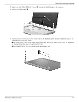
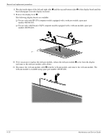
Removal and replacement procedures 5. Remove the four Phillips PM2.0x9.0 screws 1 securing the display hinges to the computer. 6. Remove the display panel 2. 7. If it is necessary to replace the display bezel or any of the display assembly internal components, remove the following screw covers and screws: 1 Two rubber screw covers on the display bezel button edge. The display rubber screw covers are included in the Display Rubber Kit, spare part number 489107-001. 2 Two Phillips PM2.0x7.0 screws on the display bezel bottom edge. Maintenance and Service Guide 4-21
-
 1
1 -
2
-
3
-
4
-
5
-
6
-
7
-
8
-
9
-
10
-
11
-
12
-
13
-
14
-
15
-
16
-
17
-
18
-
19
-
20
-
21
-
22
-
23
-
24
-
25
-
26
-
27
-
28
-
29
-
30
-
31
-
32
-
33
-
34
-
35
-
36
-
37
-
38
-
39
-
40
-
41
-
42
-
43
-
44
-
45
-
46
-
47
-
48
-
49
-
50
-
51
-
 52
52 -
 53
53 -
 54
54 -
 55
55 -
 56
56 -
 57
57 -
 58
58 -
 59
59 -
 60
60 -
 61
61 -
 62
62 -
63
-
64
-
65
-
66
-
67
-
68
-
69
-
70
-
71
-
72
-
73
-
74
-
75
-
76
-
77
-
78
-
79
-
80
-
81
-
82
-
83
-
84
-
85
-
86
-
87
-
88
-
89
-
90
-
91
-
92
-
93
-
94
-
95
-
96
-
97
-
98
-
99
-
100
-
101
-
102
-
103
-
104
-
105
-
106
-
107
-
108
-
109
-
110
-
111
-
112
-
113
-
114
-
115
-
116
-
117
-
118
-
119
-
120
-
121
-
122
-
123
-
124
-
125
-
126
-
127
-
128
-
129
-
130
 |
 |
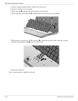
Removal and replacement procedures
Maintenance and Service Guide
4–21
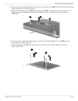
5. Remove the four Phillips PM2.0x9.0 screws
1
securing the display hinges to the computer.
6. Remove the display panel
2
.
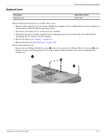
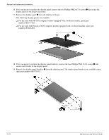
7. If it is necessary to replace the display bezel or any of the display assembly internal components, remove the
following screw covers and screws:
1
Two rubber screw covers on the display bezel button edge. The display rubber screw covers are included in
the Display Rubber Kit, spare part number 489107-001.
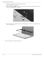
2
Two Phillips PM2.0x7.0 screws on the display bezel bottom edge.