HP HDX X18T-1200 HP HDX 18 Entertainment PC - Maintenance and Service Guide - Page 65
HP HDX X18T-1200 Manual
 |
View all HP HDX X18T-1200 manuals
Add to My Manuals
Save this manual to your list of manuals |
Page 65 highlights
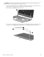
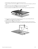
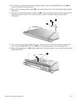
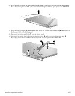
Ä CAUTION: Support the display assembly when removing the following screws. Failure to support the display assembly can result in damage to the display assembly and other computer components. 5. Remove the four Phillips PM2.5×7.0 screws 1 that secure the display assembly to the computer. Be sure to hold the display before removing the last screw to prevent damage to the display. 6. Lift the display assembly 2 straight up and remove it. 7. If it is necessary to replace the display enclosure or any of the display assembly internal components, remove the rubber screw covers 1 and the four Phillips PM2.5×7.0 screws 2 on the display bezel lower edge. Removal and replacement procedures 4-32
-
 1
1 -
2
-
3
-
4
-
5
-
6
-
7
-
8
-
9
-
10
-
11
-
12
-
13
-
14
-
15
-
16
-
17
-
18
-
19
-
20
-
21
-
22
-
23
-
24
-
25
-
26
-
27
-
28
-
29
-
30
-
31
-
32
-
33
-
34
-
35
-
36
-
37
-
38
-
39
-
40
-
41
-
42
-
43
-
44
-
45
-
46
-
47
-
48
-
49
-
50
-
51
-
52
-
53
-
54
-
55
-
56
-
57
-
58
-
59
-
 60
60 -
 61
61 -
 62
62 -
 63
63 -
 64
64 -
 65
65 -
 66
66 -
 67
67 -
 68
68 -
 69
69 -
 70
70 -
71
-
72
-
73
-
74
-
75
-
76
-
77
-
78
-
79
-
80
-
81
-
82
-
83
-
84
-
85
-
86
-
87
-
88
-
89
-
90
-
91
-
92
-
93
-
94
-
95
-
96
-
97
-
98
-
99
-
100
-
101
-
102
-
103
-
104
-
105
-
106
-
107
-
108
-
109
-
110
-
111
-
112
-
113
-
114
-
115
-
116
-
117
-
118
-
119
-
120
-
121
-
122
-
123
-
124
-
125
-
126
-
127
-
128
-
129
-
130
-
131
-
132
-
133
-
134
-
135
-
136
-
137
-
138
 |
 |
Removal and replacement procedures
4–32
Ä
CAUTION:
Support the display assembly when removing the following screws. Failure to support the display assembly can
result in damage to the display assembly and other computer components.
5. Remove the four Phillips PM2.5×7.0 screws
1
that secure the display assembly to the computer. Be sure to
hold the display before removing the last screw to prevent damage to the display.
6. Lift the display assembly
2
straight up and remove it.
7. If it is necessary to replace the display enclosure or any of the display assembly internal components, remove
the rubber screw covers
1
and the four Phillips PM2.5×7.0 screws
2
on the display bezel lower edge.