HP Indigo WS6000 Rewinder Service - Page 8
When inserted to two other pins
 |
View all HP Indigo WS6000 manuals
Add to My Manuals
Save this manual to your list of manuals |
Page 8 highlights
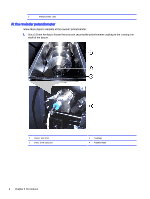
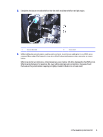
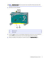
2. Straighten the dancer arm axle shaft so that the shaft and piston shaft are at right angles. 1 Dancer axle shaft 2 Piston shaft 3. While holding the potentiometer coupling with one hand, insert the two cable pins from a DVM, set to measure Ohm values (Resistance), to two pins of the 6-pin potentiometer molex connector as shown below. When inserted to two other pins, a fixed resistance value of about 5-6 KΩ is displayed on the DVM screen. When inserted between, for example, the lower white and green wire connections, the value should fluctuate as the potentiometer coupling is slightly rotated on the dancer arm axle shaft. At the rewinder potentiometer 5
-
 1
1 -
2
-
 3
3 -
 4
4 -
 5
5 -
 6
6 -
 7
7 -
 8
8 -
 9
9 -
 10
10 -
 11
11 -
 12
12 -
 13
13 -
14
-
15
-
16
-
17
-
18
-
19
-
20
-
21
-
22
-
23
-
24
-
25
-
26
-
27
-
28
-
29
-
30
-
31
-
32
-
33
-
34
-
35
-
36
-
37
-
38
-
39
-
40
-
41
-
42
-
43
-
44
-
45
-
46
-
47
-
48
-
49
-
50
-
51
-
52
-
53
-
54
-
55
-
56
-
57
-
58
-
59
-
60
-
61
-
62
-
63
-
64
-
65
-
66
-
67
-
68
-
69
-
70
-
71
-
72
-
73
-
74
-
75
-
76
-
77
-
78
-
79
-
80
-
81
-
82
-
83
-
84
-
85
-
86
-
87
-
88
 |
 |

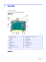
2.
Straighten the dancer arm axle shaft so that the shaft and piston shaft are at right angles.
1
Dancer axle shaft
2
Piston shaft
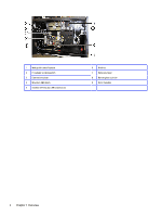
3.
While holding the potentiometer coupling with one hand, insert the two cable pins from a DVM, set to
measure Ohm values (Resistance), to two pins of the 6-pin potentiometer molex connector as shown
below.
When inserted to two other pins, a fixed resistance value of about 5-6 KΩ is displayed on the DVM screen.
When inserted between, for example, the lower white and green wire connections, the value should
fluctuate as the potentiometer coupling is slightly rotated on the dancer arm axle shaft.
At the rewinder potentiometer
5