HP InfiniBand FDR 2-port 545M Converged Networks and Fibre Channel over Ethern - Page 8
FCoE and DCB progress and challenges ahead
 |
View all HP InfiniBand FDR 2-port 545M manuals
Add to My Manuals
Save this manual to your list of manuals |
Page 8 highlights
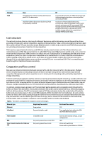
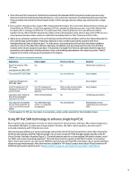
Networks become congested like traffic after an accident. When an auto accident occurs at an intersection in the center of a big city, traffic backs up on the intersection, which in turn backs up traffic in adjacent streets until nothing can move within a full square mile. This is called "congestion spreading." The methods for congestion management change with the standards employed. Table 4 shows those changes in different network enviornments and employing different congestion management technologies. Table 4. This table shows the results of different congestion management methods when end-to-end load overwhelms network capacity Congestion management technology Behavior Technology example showing that behavior can be successfully managed Drop Drop packets TCP Credit congestion spreading due to buffers not being granted on links Severely limit number of hops, or tune configuration DCB: pause at some priorities, drop at others congestion spreading on congested priorities due to per priority pause Tune application or use the QCN mechanism FCoE and DCB progress and challenges ahead FCoE at the server edge, from the CNA to the first hop switch with separate Ethernet and Fibre Channel uplinks is widely available in the industry from multiple vendors and should be considered proven. The way bandwidth is allocated between TCP traffic and FCoE traffic varies by vendor. FCoE from a CNA, through an intermediate Ethernet switch, then to a second hop switch which has separate Ethernet and Fibre Channel uplinks, is slowly becoming available. There are two key technology areas in which industry network vendors promote competing technologies for two-hop FCoE: congestion management, and FCoE Initialization Protocol (FIP) snooping. In congestion management in two hop FcoE, the way the input of the second switch manages its buffer space determines whether the switch drops TCP packets due to congestion or issues a PFC pause (part of DCB) to lossless traffic like FCoE. While it is always possible to deploy very expensive switches with very deep buffers, most organizations are likely to choose today's cost effective access layer switches with much smaller buffers inside the switch chip(s). In such designs, much attention goes into optimizing the use of limited buffer space, whether that is fixed assignment of space to ports and classes of service, or quotas for how much each of those can take from a shared pool. FIP snooping is a feature of the intermediate Ethernet switch in a two hop configuration. In simple terms, FIP snooping is part of an overall security design for first generation FcoE. It is intended to prevent a compromised server on the network from forging FCoE packets. The switch watches FIP packets and only allows FCoE traffic between endpoints that have successfully opened an FCoE connection. FIP snooping is defined in an appendix to the FC-BB-5 standard. Unfortunately, FIP snooping implementations vary so much that almost no two implementations behave identically. Next generation FCoE is in development in the FC-BB-6 committee at the time of publishing this paper. One of the concepts discussed publicly in FC-BB-6 has been a device called an FDF, which acts as a port expander to a Fibre Channel switch (or Ethernet switch running the Fibre Channel switch software). The FDF will have a much clearer set of responsibilities in the FCoE world than the Ethernet switch with FIP snooping that it will effectively replace. Native FCoE storage devices are available from some vendors, but not yet deployed widely. We expect that, just as with Fibre Channel devices today, extensive interoperability testing will be needed. Once that testing is complete one expects native FCoE storage devices will work in the tested configurations keeping in line with the FC model of interoperability. Successful implementation of FCoE through multiple hops of a data center network, or through an arbitrary network topology, requires technology that is still evolving. Interoperability will also be a challenge for at least the next several years. for the next few years, organizations should expect to spend technical resources on configuring and tuning any multi-hop network that carries FCoE traffic. Cisco has proposed a different approach to FCoE. In the Cisco model Fibre Channel traffic is passed over Ethernet, not as FCoE packets being forwarded at Layer 2 through switches, but instead passing through a FCF at Layer 3 using Fabric Shortest Path First (FSPF) at each hop. This approach calls attention to the following observations: 8
-
 1
1 -
2
-
 3
3 -
 4
4 -
 5
5 -
 6
6 -
 7
7 -
 8
8 -
 9
9 -
 10
10 -
 11
11 -
 12
12
 |
 |
