HP Integrity rx4640 Internal Cabling Guide for HP Smart Array Controllers - Page 46
Setting up RAID Cabling for IO Chassis 0 Bottom Hot Plug Hard Drives, Step 3. - user service guide
 |
View all HP Integrity rx4640 manuals
Add to My Manuals
Save this manual to your list of manuals |
Page 46 highlights
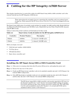
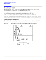
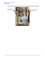
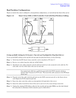
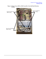
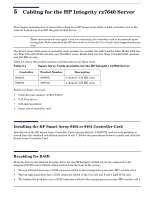
Cabling for the HP Integrity rx7620 Server Recabling for RAID Step 8. Plug the new cable from the Smart Array card Port A2 (closest to the bracket) into the mass storage connector for the top left drive. See Figure 4-3. Step 9. Plug the new cable from the Smart Array card Port A1 (closest to the center of the board) into the mass storage connector for the top right drive. See Figure 4-3. Step 10. Arrange the new cables so that all of the slack is located in the PCI area. Step 11. Fold the cable slack and wrap a Kwik Wrap around it to maintain the slack (this allows servicing of the other PCI cards). Setting up RAID Cabling for IO Chassis 0 (Bottom Hot Plug Hard Drives) To set up the RAID cabling on the bottom hot plug hard drives, do the following, from the front of the server: Step 1. Verify that the HP Smart Array 6402 or 6404 controller card is installed in PCI slot 0-8. Refer to HP Smart Array 6400 User Guide. Step 2. Retrieve one cable from the cable kit (A7027-63001). Step 3. Identify the new cable using the colored cable ties which are also contained in the cable kit (use two of the same color, one on each end). Step 4. Plug the end of the cable with the pull-tab into the SCSI connector port A1 on the Smart Array card. See Figure 4-3. Step 5. Route the other end of the cable out through the left hand side of the server. Step 6. Route the cable towards the front of the server and over to the mass storage connectors. Step 7. Unplug the existing SCSI ribbon cable for the bottom HDDs. This is the center connector ont he Mass Storage Backplane. Step 8. Plug the new cable from the Smart Array card into the mass storage connector for the bottom HDDs. Step 9. Arrange the new cables so that all the slack is located in the PCI area. Step 10. Fold the cable slack and use the Kwik Wraps to secure and maintain the slack (this allows servicing of the other PCI cards). See Figure 4-4. 42 Chapter 4
-
 1
1 -
2
-
3
-
4
-
5
-
6
-
7
-
8
-
9
-
10
-
11
-
12
-
13
-
14
-
15
-
16
-
17
-
18
-
19
-
20
-
21
-
22
-
23
-
24
-
25
-
26
-
27
-
28
-
29
-
30
-
31
-
32
-
33
-
34
-
35
-
36
-
37
-
38
-
39
-
40
-
 41
41 -
 42
42 -
 43
43 -
 44
44 -
 45
45 -
 46
46 -
 47
47 -
 48
48 -
 49
49 -
 50
50 -
 51
51 -
52
-
53
-
54
-
55
-
56
-
57
-
58
-
59
-
60
-
61
-
62
-
63
-
64
-
65
-
66
-
67
-
68
-
69
-
70
-
71
-
72
-
73
-
74
-
75
-
76
-
77
-
78
-
79
-
80
-
81
-
82
-
83
-
84
-
85
-
86
-
87
-
88
-
89
-
90
-
91
-
92
-
93
-
94
-
95
-
96
 |
 |