HP LH4r HP Netserver LH 3 Installation Roadmap - Page 2
Overview of NetServer Features, Verify Contents
 |
View all HP LH4r manuals
Add to My Manuals
Save this manual to your list of manuals |
Page 2 highlights
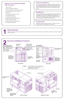
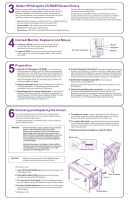
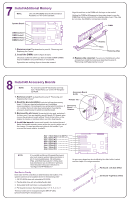
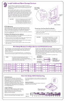
NetServer LH 3 Installation Road Map Table of Contents 1. Verify Contents 2. Overview of NetServer Features 3. Obtain HP Navigator CD-ROM Release History 4. Connect Monitor, Keyboard, and Mouse 5. Preparation 6. Removing and Replacing the Covers 7. Install Additional Memory 8. Install All Accessory Boards 9. Install Additional Mass Storage Devices 10. Replace Covers and Cables 11. Verify Installed Accessories (Optional) 12. Configure the HP NetServer Audience Assumptions This road map is intended for the person who installs, administers, and troubleshoots LAN servers. Hewlett-Packard Company assumes that you are qualified in the servicing of computer equipment and trained in recognizing hazards in products with hazardous energy levels. ESD Warning This HP NetServer contains sensitive electronic devices that can be damaged by electrostatic discharge (ESD). ESD hazards are a result of installation or service personnel failing to ground themselves properly. To be properly grounded, use a proper ESD wrist strap and work surface grounded to the HP NetServer chassis. Tools Required Installation of some accessories require a T15 TORX® or a 1/4-inch flat blade screwdriver, depending on the accessory. 1 Verify Contents Unpack and verify the contents of the shipping box against the Contents Checklist included with your HP NetServer. If anything is missing or damaged, contact your reseller. 2 Overview of NetServer Features Front Panel Power Switch Non-Hot-Swap Shelves: Display Reset Switch I/O Connectors: Shelf 1 (Flexible Disk Drive) Shelf 2 (CD-ROM Drive) Shelf 3 (Empty) Bezel Lock Keyboard Lock Switch Remote Management Status Lights Serial B Display Control Buttons Serial A Shelf 4 (Empty) Parallel Mouse Keyboard Hot-Swap Mass Storage Expansion Bay (Empty) Hot-Swap Mass Storage Cage Monitor Hot-Swap Power Supply Modules AC Power Connector Front View Rear View NOTE Power redundancy requires three power supply modules. No redundancy is available with two modules. Accessory Board Sockets I/O Board System Board Accessory Board Slot Covers Hot-Swap Power Supply Expansion Bay (Empty) Hot-Swap Power Supply Expansion Bay (Empty) Redundant Fan Expansion Bay (Empty) Left Front View Right Front View Backplane Hot-Swap Power Supply Cage
-
 1
1 -
 2
2 -
 3
3 -
 4
4 -
 5
5 -
 6
6
 |
 |
