HP LH4r HP Netserver LH 3r Installation Roadmap - Page 3
Obtain HP Navigator CD-ROM Release History, Removing and Replacing the Covers, Install Additional
 |
View all HP LH4r manuals
Add to My Manuals
Save this manual to your list of manuals |
Page 3 highlights
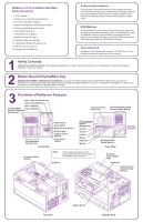
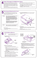
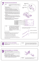
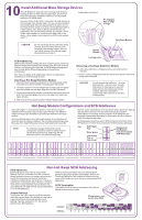
4 Obtain HP Navigator CD-ROM Release History Before you begin installing your HP NetServer, ensure that you have the latest version of the software by obtaining the current HP operating system (NOS) manufacturer to access the necessary Internet, BBS, or CompuServe site containing the drivers and software. NetServer Navigator CD-ROM release history. It describes the latest software updates to each release of the Navigator CD-ROM, as well as instructions for obtaining the current release. You can obtain the release history from one of the HP NetServer information resources listed here. ! Fax-Call HP's fax system at 1-800-333-1917 (or 1-208-344-4809 from your fax machine), and request document number 6005 ! Internet WWW-http://www.hp.com/netserver/servsup ! Internet FTP-ftp://ftp.hp.com/pub/servers To obtain drivers and utilities for the non-HP components of your ! CompuServe-GO HPPC; download 6005.txt from the NetServer library system, follow the directions provided by the component or network 5 Removing and Replacing the Covers If you are installing accessory cards or mass storage, remove cover 1. If you are installing memory, remove cover 3. To install some options, you will need a flat 1/4-inch screwdriver or a T15 TORX driver, depending on the accessory. 2. Loosen the thumbscrew at the front of the cover and pull the cover forward, using the handle on the cover, and then lift it off the chassis. WARNING Before removing cover(s), always disconnect the power cord and unplug telephone cables. Disconnect the power cord to avoid exposure to high energy levels that may cause burns when parts are short-circuited by metal objects, such as tools or jewelry. Disconnect telephone cables to avoid exposure to shock hazard from telephone ringing voltages. Note that the power switch does not turn off the standby power. Disconnect the power cord to turn off standby power. If the backlight on the LCD display is on, standby power is on. CAUTION Wear a wrist strap and use a static-dissipating work surface connected to the chassis at all times. To remove a cover: 1. Turn off the HP NetServer and disconnect all power and telephone cords. Cover 1 Cover 2 Thumbscrews Cover 3 To replace a cover: 1. Insert the tabs inside the cover into the slots on the chassis and slide the side cover toward the rear. Tighten the thumbscrew at the front of the cover. 2. Replace all power, telephone, and I/O cables. 6 Install Additional Memory NOTE Use only HP DIMMs listed in HP Information Assistant or in HP Order Assistant. 1. Remove cover 2 as described in panel 5, "Removing and Replacing the Covers." Metal support must be OFF work surface; system board must lie flat. System Board DIMM 0 DIMM 1 DIMM 2 DIMM 3 System Board Retaining Latches 2. Remove the system board: A. Disconnect all I/O cables from the system board. B. Lift the retaining latches to release the system board from its socket. C. Slide the system board out of the NetServer and place it component-side up on the antistatic mat. Lay the system board flat, with the metal crosspiece on the top rear corner of the system board extending off the work surface (see figure, above right). 3. Install the DIMMs (refer to figure at right): Choose a socket into which you want to install a DIMM. DIMMs may be installed in any combination, in any socket. Spread the two retaining clips on the socket outward. Align the notches on the DIMM with the keys on the socket. Holding the DIMM at 90 degrees to the system board, press the DIMM fully into the socket until the retaining clips close. If the clips do not close, the DIMM is not inserted correctly. Static-dissipating Work Surface 4. Reinstall the system board: Insert the system board into the plastic guides in the chassis. Extend the retaining latches while lowering the board until it touches its socket on the backplane. Close the retaining latches until the system board is seated firmly in its slot. Connect all I/O cables to the rear of the system board. 5. Replace the cover(s): If you are not installing any other accessories, replace the cover(s) as described in panel 5, "Removing and Replacing the Covers." DIMM Notches Keys Retaining Clips
-
 1
1 -
 2
2 -
 3
3 -
 4
4 -
 5
5 -
 6
6
 |
 |
