HP LH4r HP Netserver LH 3r Installation Roadmap - Page 4
Install All Accessory Boards, Replace Covers and Cables, Install the NetServer in the Rack
 |
View all HP LH4r manuals
Add to My Manuals
Save this manual to your list of manuals |
Page 4 highlights
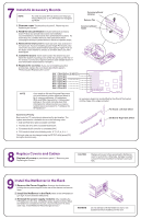
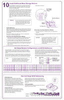
7 Install All Accessory Boards NOTE For a list of boards HP has tested, see Help topic "Tested Parts List" on the HP NetServer Navigator CD-ROM. Accessory Board Retainer Release Tab 1. Remove cover 1 as described in panel 5, "Removing and Replacing the Covers." 2. Read the documentation included with each accessory board. Follow any special instructions and installation recommendations. Some boards have preferred slot locations. If a board does not, consider the boot order (see below) when choosing the accessory board socket in which to install the board. 3. Remove the slot cover for each slot to be used, and store it for future use. If you are installing any full-length PCI boards, also remove the accessory board retainer (see figure at right). Push on the button on the retainer to release it, and then slide it out of the board guide. 4. Install the board: Insert each board in the desired slot and fasten the board's mounting screw at the slot opening at the rear of the chassis. Connect any required cables to each adapter board. If you removed the board retainer, reinstall it. 5. Replace the cover(s): If you are not installing any other accessories, replace the cover(s) as described in panel 5, "Removing and Replacing the Covers." Slot 1 16-bit ISA or 32-bit PCI Slot 2 32-bit PCI Slot 3 32-bit PCI Slot 4 32-bit PCI Slot 5 32-bit PCI Slot 6 32-bit PCI Slot 7 32-bit PCI Slot 8 32-bit PCI Accessory Board Guide NOTE If you install an ISA non-Plug-and-Play board, you must reserve system resources (some or all of: memory addresses, I/O addresses, IRQs, and DMA channels) for it. Note jumper settings on the board and write down that information for reference when you reserve system resources in panel 12, "Configure the HP NetServer." An accessory board can be identified by the offset of the bracket and the shape of the edge connector: PCI Board- Left-Side Offset Boot Device Priority Boot order for PCI controllers is determined by slot location. The system searches for a bootable device in the following order: 1. IDE CD-ROM drive with a bootable CD-ROM. 2. Flexible disk drive with a bootable flexible disk. 3. Embedded SCSI controller or embedded DAC. 4. PCI boards in slots in the following order: 8, 7, 6, 5, 4, 3, 2, 1. This boot order can be changed using the SETUP utility (press [F2] during the boot process). ISA Board- Right-Side Offset 8 Replace Covers and Cables Replace all covers as described in panel 5, "Removing and Replacing the Covers." CAUTION Replace all covers before operating the NetServer, even for a short time. Otherwise, damage to system components may result due to improper cooling air flow. 9 Install the NetServer in the Rack 1. Remove the Power Supplies: Unscrew the thumbscrews holding the two power supplies in the rear of the chassis and remove them. 2. Install the NetServer in the Rack: Refer to the HP NetServer LH 3/LH 3r User Guide for instructions. 3. Reinstall the power supply modules: After installing the HP NetServer in the rack, reinstall the power supply modules. When the NetServer is installed in the rack, resume with panel 10 of this road map, "Install Additional Mass Storage Devices." WARNING Do not attempt to lift this NetServer alone. Get assistance before installing it in the rack.
-
 1
1 -
 2
2 -
 3
3 -
 4
4 -
 5
5 -
 6
6
 |
 |
