HP LaserJet 3300 Service Manual - Page 145
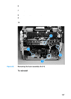
To reinstall,
 |
View all HP LaserJet 3300 manuals
Add to My Manuals
Save this manual to your list of manuals |
Page 145 highlights
3 Remove five screws (callout 1). 21 Figure 60. Removing the formatter (2 of 3) 4 Rotate the bottom of the formatter up and off of the hooks on the chassis and begin to remove it. After removing the bottom of the formatter, disconnect the two flat flexible cables from connectors at the top of the formatter, and unplug the scanner motor cable from the formatter (callout 1). 21 Figure 61. EN Removing the formatter (3 of 3) To reinstall When you reconnect the bottom cable, make sure you lock the ZIF connector at the bottom of the formatter back into place. Printer assemblies 143
-
 1
1 -
2
-
3
-
4
-
5
-
6
-
7
-
8
-
9
-
10
-
11
-
12
-
13
-
14
-
15
-
16
-
17
-
18
-
19
-
20
-
21
-
22
-
23
-
24
-
25
-
26
-
27
-
28
-
29
-
30
-
31
-
32
-
33
-
34
-
35
-
36
-
37
-
38
-
39
-
40
-
41
-
42
-
43
-
44
-
45
-
46
-
47
-
48
-
49
-
50
-
51
-
52
-
53
-
54
-
55
-
56
-
57
-
58
-
59
-
60
-
61
-
62
-
63
-
64
-
65
-
66
-
67
-
68
-
69
-
70
-
71
-
72
-
73
-
74
-
75
-
76
-
77
-
78
-
79
-
80
-
81
-
82
-
83
-
84
-
85
-
86
-
87
-
88
-
89
-
90
-
91
-
92
-
93
-
94
-
95
-
96
-
97
-
98
-
99
-
100
-
101
-
102
-
103
-
104
-
105
-
106
-
107
-
108
-
109
-
110
-
111
-
112
-
113
-
114
-
115
-
116
-
117
-
118
-
119
-
120
-
121
-
122
-
123
-
124
-
125
-
126
-
127
-
128
-
129
-
130
-
131
-
132
-
133
-
134
-
135
-
136
-
137
-
138
-
139
-
 140
140 -
 141
141 -
 142
142 -
 143
143 -
 144
144 -
 145
145 -
 146
146 -
 147
147 -
 148
148 -
 149
149 -
 150
150 -
151
-
152
-
153
-
154
-
155
-
156
-
157
-
158
-
159
-
160
-
161
-
162
-
163
-
164
-
165
-
166
-
167
-
168
-
169
-
170
-
171
-
172
-
173
-
174
-
175
-
176
-
177
-
178
-
179
-
180
-
181
-
182
-
183
-
184
-
185
-
186
-
187
-
188
-
189
-
190
-
191
-
192
-
193
-
194
-
195
-
196
-
197
-
198
-
199
-
200
-
201
-
202
-
203
-
204
-
205
-
206
-
207
-
208
-
209
-
210
-
211
-
212
-
213
-
214
-
215
-
216
-
217
-
218
-
219
-
220
-
221
-
222
-
223
-
224
-
225
-
226
-
227
-
228
-
229
-
230
-
231
-
232
-
233
-
234
-
235
-
236
-
237
-
238
-
239
-
240
-
241
-
242
-
243
-
244
-
245
-
246
-
247
-
248
-
249
-
250
-
251
-
252
-
253
-
254
-
255
-
256
-
257
-
258
-
259
-
260
-
261
-
262
-
263
-
264
-
265
-
266
-
267
-
268
-
269
-
270
-
271
-
272
-
273
-
274
-
275
-
276
-
277
-
278
-
279
-
280
-
281
-
282
-
283
-
284
-
285
-
286
-
287
-
288
-
289
-
290
-
291
 |
 |
EN
Printer assemblies
143
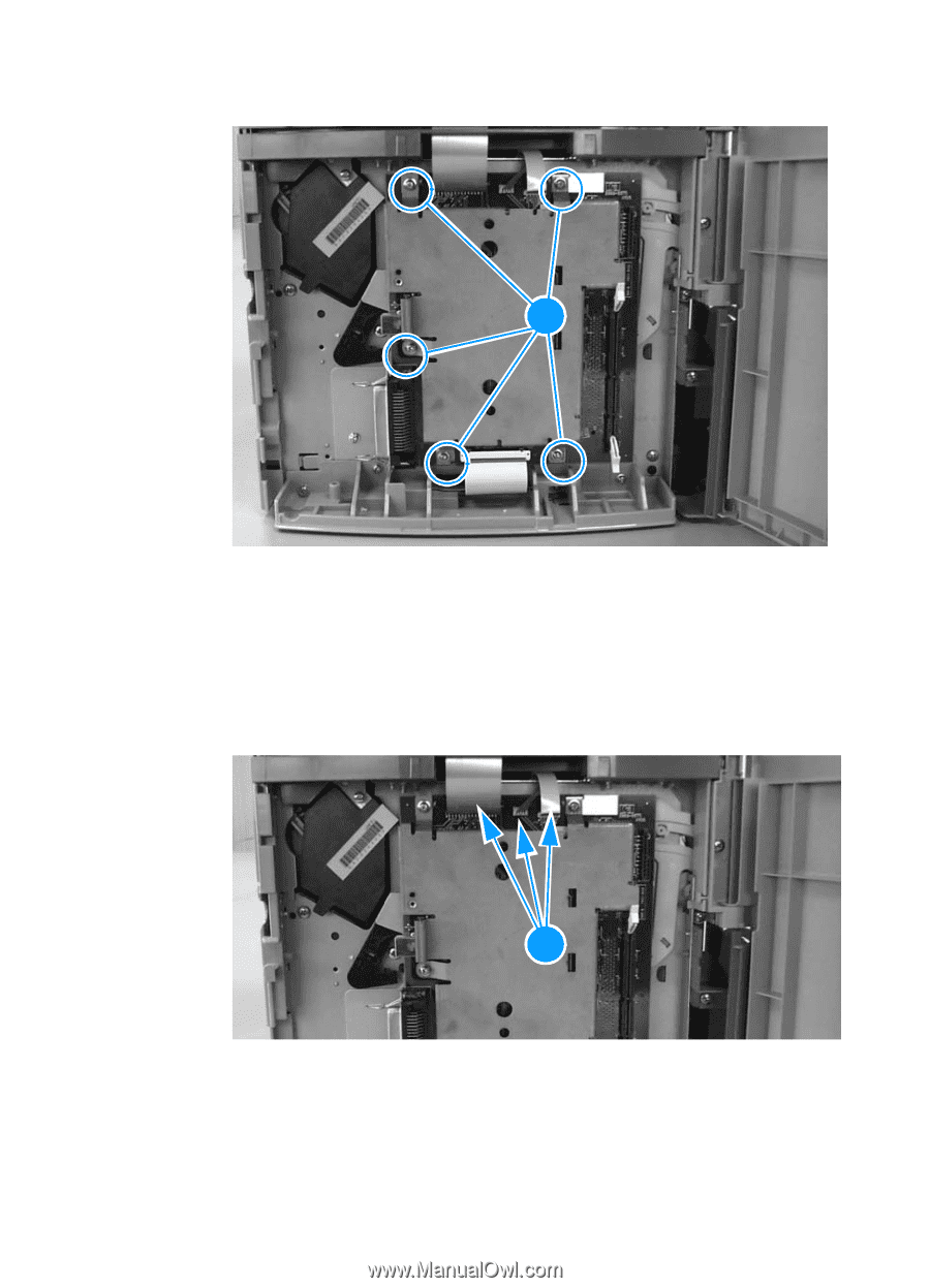
3
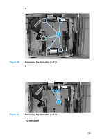
Remove five screws (callout 1).
Figure 60.
Removing the formatter (2 of 3)
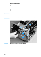
4
Rotate the bottom of the formatter up and off of the hooks on the
chassis and begin to remove it. After removing the bottom of the
formatter, disconnect the two flat flexible cables from connectors
at the top of the formatter, and unplug the scanner motor cable
from the formatter (callout 1).
Figure 61.
Removing the formatter (3 of 3)
To reinstall
When you reconnect the bottom cable, make sure you lock the ZIF
connector at the bottom of the formatter back into place.
2
1
2
1