HP Mini 210-2100 HP Mini 210 - Maintenance and Service Guide - Page 42
Component replacement procedures, Computer feet
 |
View all HP Mini 210-2100 manuals
Add to My Manuals
Save this manual to your list of manuals |
Page 42 highlights
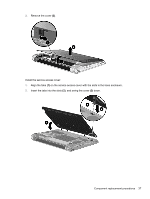
Component replacement procedures This chapter provides removal and replacement procedures. There are as many as 33 screws, in 5 different sizes, that must be removed, replaced, or loosened when servicing the computer. Make special note of each screw size and location during removal and replacement. Computer feet The computer feet are adhesive-backed rubber pads. The feet are included in the Rubber Feet Kit, spare part number 622352-001. There are 4 rubber feet that attach to the base enclosure in the locations shown in the following illustration. 32 Chapter 4 Removal and replacement procedures
-
 1
1 -
2
-
3
-
4
-
5
-
6
-
7
-
8
-
9
-
10
-
11
-
12
-
13
-
14
-
15
-
16
-
17
-
18
-
19
-
20
-
21
-
22
-
23
-
24
-
25
-
26
-
27
-
28
-
29
-
30
-
31
-
32
-
33
-
34
-
35
-
36
-
 37
37 -
 38
38 -
 39
39 -
 40
40 -
 41
41 -
 42
42 -
 43
43 -
 44
44 -
 45
45 -
 46
46 -
 47
47 -
48
-
49
-
50
-
51
-
52
-
53
-
54
-
55
-
56
-
57
-
58
-
59
-
60
-
61
-
62
-
63
-
64
-
65
-
66
-
67
-
68
-
69
-
70
-
71
-
72
-
73
-
74
-
75
-
76
-
77
-
78
-
79
-
80
-
81
-
82
-
83
-
84
-
85
-
86
-
87
-
88
-
89
-
90
-
91
-
92
-
93
-
94
-
95
-
96
-
97
-
98
-
99
-
100
-
101
-
102
-
103
-
104
-
105
-
106
-
107
-
108
-
109
 |
 |

Component replacement procedures
This chapter provides removal and replacement procedures.
There are as many as 33 screws, in 5 different sizes, that must be removed, replaced, or loosened
when servicing the computer. Make special note of each screw size and location during removal and
replacement.
Computer feet
The computer feet are adhesive-backed rubber pads. The feet are included in the Rubber Feet Kit,
spare part number 622352-001. There are 4 rubber feet that attach to the base enclosure in the
locations shown in the following illustration.
32
Chapter 4
Removal and replacement procedures