HP Mini 210-4001xx HP Mini 210, HP Mini 110, Compaq Mini CQ10 - Maintenance an - Page 77
that fits on the right side has an L-shaped, alignment notch. When installing the rubber feet
 |
View all HP Mini 210-4001xx manuals
Add to My Manuals
Save this manual to your list of manuals |
Page 77 highlights
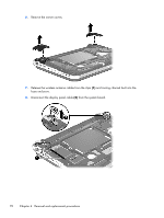
5. Remove the seven Phillips PM2.0×5.0 screws (2) that secure the top cover and the corner covers to the base enclosure. NOTE: The rubber feet are notched differently. The rubber foot (1) that fits on the left side has a rectangular alignment notch. The rubber foot (2) that fits on the right side has an "L"-shaped alignment notch. When installing the rubber feet, align them according to the side of the computer on which they should be installed. Component replacement procedures 69
-
 1
1 -
2
-
3
-
4
-
5
-
6
-
7
-
8
-
9
-
10
-
11
-
12
-
13
-
14
-
15
-
16
-
17
-
18
-
19
-
20
-
21
-
22
-
23
-
24
-
25
-
26
-
27
-
28
-
29
-
30
-
31
-
32
-
33
-
34
-
35
-
36
-
37
-
38
-
39
-
40
-
41
-
42
-
43
-
44
-
45
-
46
-
47
-
48
-
49
-
50
-
51
-
52
-
53
-
54
-
55
-
56
-
57
-
58
-
59
-
60
-
61
-
62
-
63
-
64
-
65
-
66
-
67
-
68
-
69
-
70
-
71
-
 72
72 -
 73
73 -
 74
74 -
 75
75 -
 76
76 -
 77
77 -
 78
78 -
 79
79 -
 80
80 -
 81
81 -
 82
82 -
83
-
84
-
85
-
86
-
87
-
88
-
89
-
90
-
91
-
92
-
93
-
94
-
95
-
96
-
97
-
98
-
99
-
100
-
101
-
102
-
103
-
104
-
105
-
106
-
107
-
108
-
109
-
110
-
111
-
112
-
113
-
114
 |
 |

5.
Remove the seven Phillips PM2.0×5.0 screws
(2)
that secure the top cover and the corner covers
to the base enclosure.
NOTE:
The rubber feet are notched differently. The rubber foot
(1)
that fits on the left side has a
rectangular alignment notch. The rubber foot
(2)
that fits on the right side has an “L”-shaped
alignment notch. When installing the rubber feet, align them according to the side of the computer
on which they should be installed.
Component replacement procedures
69