HP Mini 5102 HP Mini 5102 - Maintenance and Service Guide - Page 81
System board, Remove the Phillips PM2.0×3.0 screw - atom
 |
View all HP Mini 5102 manuals
Add to My Manuals
Save this manual to your list of manuals |
Page 81 highlights
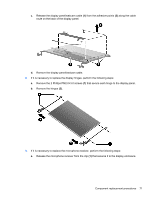
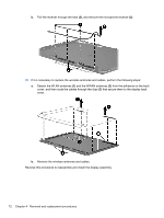
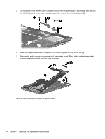
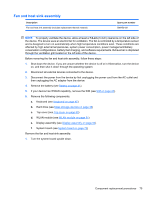
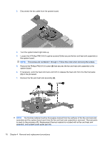
System board Description Spare part number System board (includes processor and replacement thermal material) ● Includes Intel Atom N470 1.83-GHz processor, 512-KB Level 2 cache, 667-MHz front-side bus 598449-001 (FSB) ● Includes Intel Atom N470 1.83-GHz processor, 512-KB Level 2 cache, 667-MHz front-side bus 598450-001 (FSB) for use in the People's Republic of China ● Includes Intel Atom N450 1.66-GHz processor, 512-KB Level 2 cache, 667-MHz front-side bus 598447-001 (FSB) ● Includes Intel Atom N450 1.66-GHz processor, 512-KB Level 2 cache, 667-MHz front-side bus 598448-001 (FSB) for use in the People's Republic of China Before removing the system board, follow these steps: 1. Shut down the device. If you are unsure whether the device is off or in Hibernation, turn the device on, and then shut it down through the operating system. 2. Disconnect all external devices connected to the device. 3. Disconnect the power from the device by first unplugging the power cord from the AC outlet and then unplugging the AC adapter from the device. 4. Remove the battery (see Battery on page 41). 5. If your device has WWAN capability, remove the SIM (see SIM on page 42). 6. Remove the following components: a. Keyboard (see Keyboard on page 45) b. Hard drive (see Mass storage devices on page 48) c. Top cover (see Top cover on page 55) d. Display assembly (see Display assembly on page 64) When replacing the system board, be sure that the following components are removed from the defective system board and installed on the replacement system board: ● WLAN module (see WLAN module on page 51) ● WWAN module, if included (see WWAN module on page 59) ● Bluetooth module (see Bluetooth module on page 62) Remove the system board: 1. Remove the Phillips PM2.0×3.0 screw (1) that secures the bracket over the audio connectors to the base enclosure, and then remove the bracket (2). 2. Remove the bracket that sec Component replacement procedures 73
-
 1
1 -
2
-
3
-
4
-
5
-
6
-
7
-
8
-
9
-
10
-
11
-
12
-
13
-
14
-
15
-
16
-
17
-
18
-
19
-
20
-
21
-
22
-
23
-
24
-
25
-
26
-
27
-
28
-
29
-
30
-
31
-
32
-
33
-
34
-
35
-
36
-
37
-
38
-
39
-
40
-
41
-
42
-
43
-
44
-
45
-
46
-
47
-
48
-
49
-
50
-
51
-
52
-
53
-
54
-
55
-
56
-
57
-
58
-
59
-
60
-
61
-
62
-
63
-
64
-
65
-
66
-
67
-
68
-
69
-
70
-
71
-
72
-
73
-
74
-
75
-
 76
76 -
 77
77 -
 78
78 -
 79
79 -
 80
80 -
 81
81 -
 82
82 -
 83
83 -
 84
84 -
 85
85 -
 86
86 -
87
-
88
-
89
-
90
-
91
-
92
-
93
-
94
-
95
-
96
-
97
-
98
-
99
-
100
-
101
-
102
-
103
-
104
-
105
-
106
-
107
-
108
-
109
-
110
-
111
-
112
-
113
-
114
-
115
-
116
-
117
-
118
-
119
-
120
-
121
-
122
-
123
-
124
-
125
-
126
-
127
-
128
-
129
-
130
-
131
-
132
-
133
-
134
-
135
-
136
-
137
-
138
-
139
-
140
-
141
-
142
-
143
-
144
-
145
-
146
-
147
 |
 |
