HP Nx5000 HP Compaq nx5000 Notebook PC - Maintenance and Service Guide - Page 121
communications board to the socket. The board rises up., Pull the board
 |
View all HP Nx5000 manuals
Add to My Manuals
Save this manual to your list of manuals |
Page 121 highlights
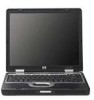
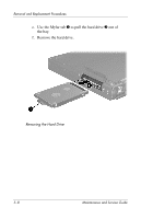
Removal and Replacement Procedures 6. Disconnect the 2 antenna cables 1 from the Mini PCI communications board. Note that the longer cable connects to the rear antenna terminal and the shorter antenna cable connects to the front antenna terminal. 7. Spread the retaining tabs 2 that secure the Mini PCI communications board to the socket. The board rises up. 8. Pull the board 3 away from the socket at a 45-degree angle. Disconnecting the Cables and Removing the Mini PCI Communications Board Reverse the above procedure to install a Mini PCI communications board. Å WARNING: To prevent an unresponsive system and the display of a warning message, install only a Mini PCI device authorized for use in your notebook by the governmental agency that regulates wireless devices in your country. If you install a device and then receive a warning message, remove the device to restore notebook functionality. Then contact Customer Care. Maintenance and Service Guide 5-13
-
 1
1 -
2
-
3
-
4
-
5
-
6
-
7
-
8
-
9
-
10
-
11
-
12
-
13
-
14
-
15
-
16
-
17
-
18
-
19
-
20
-
21
-
22
-
23
-
24
-
25
-
26
-
27
-
28
-
29
-
30
-
31
-
32
-
33
-
34
-
35
-
36
-
37
-
38
-
39
-
40
-
41
-
42
-
43
-
44
-
45
-
46
-
47
-
48
-
49
-
50
-
51
-
52
-
53
-
54
-
55
-
56
-
57
-
58
-
59
-
60
-
61
-
62
-
63
-
64
-
65
-
66
-
67
-
68
-
69
-
70
-
71
-
72
-
73
-
74
-
75
-
76
-
77
-
78
-
79
-
80
-
81
-
82
-
83
-
84
-
85
-
86
-
87
-
88
-
89
-
90
-
91
-
92
-
93
-
94
-
95
-
96
-
97
-
98
-
99
-
100
-
101
-
102
-
103
-
104
-
105
-
106
-
107
-
108
-
109
-
110
-
111
-
112
-
113
-
114
-
115
-
 116
116 -
 117
117 -
 118
118 -
 119
119 -
 120
120 -
 121
121 -
 122
122 -
 123
123 -
 124
124 -
 125
125 -
 126
126 -
127
-
128
-
129
-
130
-
131
-
132
-
133
-
134
-
135
-
136
-
137
-
138
-
139
-
140
-
141
-
142
-
143
-
144
-
145
-
146
-
147
-
148
-
149
-
150
-
151
-
152
-
153
-
154
-
155
-
156
-
157
-
158
-
159
-
160
-
161
-
162
-
163
-
164
-
165
-
166
-
167
-
168
-
169
-
170
-
171
-
172
-
173
-
174
-
175
-
176
-
177
-
178
-
179
-
180
-
181
-
182
-
183
-
184
-
185
-
186
-
187
-
188
-
189
-
190
-
191
-
192
-
193
-
194
-
195
-
196
-
197
-
198
-
199
-
200
-
201
-
202
-
203
-
204
-
205
-
206
-
207
-
208
-
209
-
210
-
211
-
212
-
213
-
214
-
215
-
216
-
217
-
218
-
219
-
220
-
221
-
222
-
223
 |
 |
