HP Nx5000 HP Compaq nx5000 Notebook PC - Maintenance and Service Guide - Page 139
Fan Assembly
 |
View all HP Nx5000 manuals
Add to My Manuals
Save this manual to your list of manuals |
Page 139 highlights
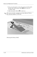
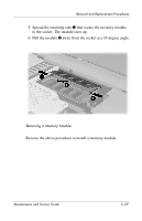
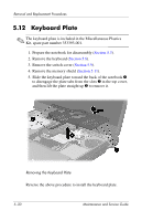
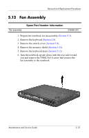
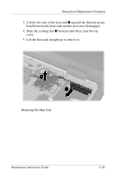
Removal and Replacement Procedures 5.13 Fan Assembly Fan assembly Spare Part Number Information 345065-001 1. Prepare the notebook for disassembly (Section 5.3). 2. Remove the keyboard (Section 5.8). 3. Remove the switch cover (Section 5.9). 4. Remove the memory shield (Section 5.11). 5. Remove the keyboard plate (Section 5.12). 6. Turn the notebook upside down with the rear side toward you and remove the T8M2.5x5.0 screw that secures the fan assembly to the notebook. Maintenance and Service Guide 5-31
-
 1
1 -
2
-
3
-
4
-
5
-
6
-
7
-
8
-
9
-
10
-
11
-
12
-
13
-
14
-
15
-
16
-
17
-
18
-
19
-
20
-
21
-
22
-
23
-
24
-
25
-
26
-
27
-
28
-
29
-
30
-
31
-
32
-
33
-
34
-
35
-
36
-
37
-
38
-
39
-
40
-
41
-
42
-
43
-
44
-
45
-
46
-
47
-
48
-
49
-
50
-
51
-
52
-
53
-
54
-
55
-
56
-
57
-
58
-
59
-
60
-
61
-
62
-
63
-
64
-
65
-
66
-
67
-
68
-
69
-
70
-
71
-
72
-
73
-
74
-
75
-
76
-
77
-
78
-
79
-
80
-
81
-
82
-
83
-
84
-
85
-
86
-
87
-
88
-
89
-
90
-
91
-
92
-
93
-
94
-
95
-
96
-
97
-
98
-
99
-
100
-
101
-
102
-
103
-
104
-
105
-
106
-
107
-
108
-
109
-
110
-
111
-
112
-
113
-
114
-
115
-
116
-
117
-
118
-
119
-
120
-
121
-
122
-
123
-
124
-
125
-
126
-
127
-
128
-
129
-
130
-
131
-
132
-
133
-
 134
134 -
 135
135 -
 136
136 -
 137
137 -
 138
138 -
 139
139 -
 140
140 -
 141
141 -
 142
142 -
 143
143 -
 144
144 -
145
-
146
-
147
-
148
-
149
-
150
-
151
-
152
-
153
-
154
-
155
-
156
-
157
-
158
-
159
-
160
-
161
-
162
-
163
-
164
-
165
-
166
-
167
-
168
-
169
-
170
-
171
-
172
-
173
-
174
-
175
-
176
-
177
-
178
-
179
-
180
-
181
-
182
-
183
-
184
-
185
-
186
-
187
-
188
-
189
-
190
-
191
-
192
-
193
-
194
-
195
-
196
-
197
-
198
-
199
-
200
-
201
-
202
-
203
-
204
-
205
-
206
-
207
-
208
-
209
-
210
-
211
-
212
-
213
-
214
-
215
-
216
-
217
-
218
-
219
-
220
-
221
-
222
-
223
 |
 |

Removal and Replacement Procedures
Maintenance and Service Guide
5–31
5.13
Fan Assembly
1. Prepare the notebook for disassembly (
Section 5.3
).
2. Remove the keyboard (
Section 5.8
).
3. Remove the switch cover (
Section 5.9
).
4. Remove the memory shield (
Section 5.11
).
5. Remove the keyboard plate (
Section 5.12
).
6. Turn the notebook upside down with the rear side toward
you and remove the T8M2.5x5.0 screw that secures the
fan assembly to the notebook.
Spare Part Number Information
Fan assembly
345065-001