HP P6000 HP StorageWorks disk enclosure VRM replacement instructions (504218-0 - Page 2
Verifying component failure, Removing the VRM, Green, Amber - review
 |
View all HP P6000 manuals
Add to My Manuals
Save this manual to your list of manuals |
Page 2 highlights
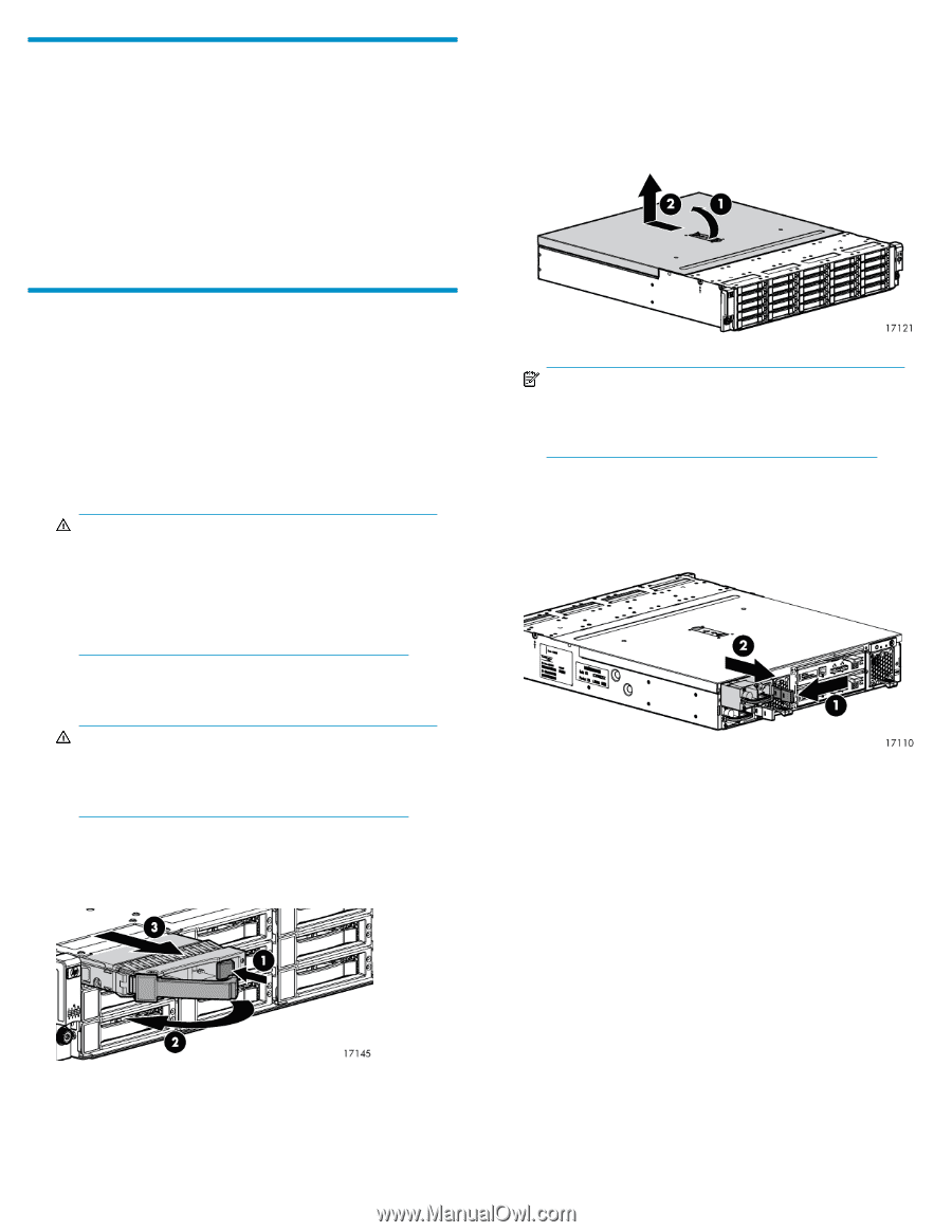
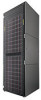
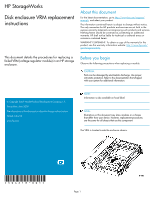
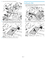
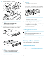
Verifying component failure Analyze any failure messages received in the system logs. Review HP fault monitoring software for provided recommended failure information and recommended actions. • Check the enclosure status LED (if VRM has failed it will be amber) • Check the enclosure status LED. • Green = Normal operation. • Amber = Fault condition • Off = Fan unseated from connector or failed. 7. Remove the top access cover. a. Lift the access panel latch (1). The access panel will slightly disengage from the enclosure. b. Slide the access panel to the rear (2) and lift away from the chassis. Removing the VRM 1. Schedule a maintenance window. 2. Stop all I/O to the enclosure. 3. Power down the enclosure by pressing and holding the On/Standby button on the rear of disk enclosure, until the system power LED changes from green to amber. 4. Remove all cabling from the rear of the enclosure. Ensure all cabling is marked to facilitate re-cabling later. WARNING! A disk enclosure fully populated is heavy. Prior to removing the enclosure from the rack, remove each disk and label it with its bay number. Place each disk on a clean surface. If this is not possible, two people are required to remove the enclosure from the rack to prevent injury. NOTE: A Torx tool with T-10 and T-15 ends is provided inside the enclosure chassis, on top of the I/O module housing. 8. Disengage the two power supplies from the internal connections to the VRM by pressing the power supply mounting latch towards the power supply and pulling the module slightly out of the enclosure (2). 5. Remove hard drives from the enclosure. WARNING! When removing drives keep them in order. They will need to be returned to the same slots they were removed from at the time of replacement. Press the release button on the drive lever (1), and rotate the lever to the left (2). Then, pull out and remove the disk drive from the drive bays (3). 6. Loosen the thumbscrews that secure the enclosure to the front of the rack, and remove the enclosure from the rack. Page 2
-
 1
1 -
 2
2 -
 3
3 -
 4
4
 |
 |