HP Pavilion 14-b130us HP Pavilion TouchSmart 14 Ultrabook HP Pavilion TouchSma - Page 82
cooling tubes. The tubes bend easily., To prevent damage to the cooling tubes
 |
View all HP Pavilion 14-b130us manuals
Add to My Manuals
Save this manual to your list of manuals |
Page 82 highlights
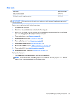
2. Remove the heat sink. If you have an UMA graphics heat sink, go to step c. a. Loosen all of the captive screws (1) and (2) and then lift the switchable discrete graphics heat sink (3) from the system board. CAUTION: To prevent damage to the cooling tubes, do not lift the assembly by the cooling tubes. The tubes bend easily. b. Thoroughly clean the thermal connections (1) and (3) on the system board and the heat sink (2) and (4) before replacing a heat sink onto a system board. Continue to step 3. 74 Chapter 5 Removal and replacement procedures
-
 1
1 -
2
-
3
-
4
-
5
-
6
-
7
-
8
-
9
-
10
-
11
-
12
-
13
-
14
-
15
-
16
-
17
-
18
-
19
-
20
-
21
-
22
-
23
-
24
-
25
-
26
-
27
-
28
-
29
-
30
-
31
-
32
-
33
-
34
-
35
-
36
-
37
-
38
-
39
-
40
-
41
-
42
-
43
-
44
-
45
-
46
-
47
-
48
-
49
-
50
-
51
-
52
-
53
-
54
-
55
-
56
-
57
-
58
-
59
-
60
-
61
-
62
-
63
-
64
-
65
-
66
-
67
-
68
-
69
-
70
-
71
-
72
-
73
-
74
-
75
-
76
-
 77
77 -
 78
78 -
 79
79 -
 80
80 -
 81
81 -
 82
82 -
 83
83 -
 84
84 -
 85
85 -
 86
86 -
 87
87 -
88
-
89
-
90
-
91
-
92
-
93
-
94
-
95
-
96
-
97
-
98
-
99
-
100
-
101
-
102
-
103
-
104
-
105
-
106
-
107
-
108
-
109
-
110
-
111
-
112
-
113
-
114
-
115
-
116
-
117
-
118
-
119
 |
 |

2.
Remove the heat sink. If you have an UMA graphics heat sink, go to step c.
a.
Loosen all of the captive screws
(1)
and
(2)
and then lift the switchable discrete graphics
heat sink
(3)
from the system board.
CAUTION:
To prevent damage to the cooling tubes, do not lift the assembly by the
cooling tubes. The tubes bend easily.
b.
Thoroughly clean the thermal connections
(1)
and
(3)
on the system board and the heat
sink
(2)
and
(4)
before replacing a heat sink onto a system board. Continue to step 3.
74
Chapter 5
Removal and replacement procedures