HP Pavilion 15-ab200 Pavilion Notebook AMD Maintenance and Service Guide - Page 79
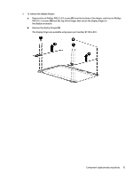
Remove the two Phillips PM2.0×1.5 screws, disconnect the display cable
 |
View all HP Pavilion 15-ab200 manuals
Add to My Manuals
Save this manual to your list of manuals |
Page 79 highlights
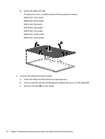
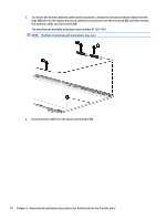
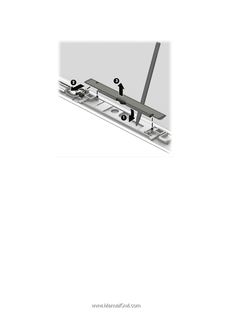
d. Remove the webcam/microphone module from the display (3). The webcam for touch displays is available using spare part number 810961-001. 3. To remove the display panel: a. Lift the tape that secures the display cable to the connector on the back of the panel (1), and then disconnect the display cable (2). b. Remove the two Phillips PM2.0×1.5 screws (3) that secure the display panel to the bottom of the enclosure. c. Remove the two Phillips PM2.0×2.0 screws (4) that secure the display panel to the top of the enclosure. Component replacement procedures 71
-
 1
1 -
2
-
3
-
4
-
5
-
6
-
7
-
8
-
9
-
10
-
11
-
12
-
13
-
14
-
15
-
16
-
17
-
18
-
19
-
20
-
21
-
22
-
23
-
24
-
25
-
26
-
27
-
28
-
29
-
30
-
31
-
32
-
33
-
34
-
35
-
36
-
37
-
38
-
39
-
40
-
41
-
42
-
43
-
44
-
45
-
46
-
47
-
48
-
49
-
50
-
51
-
52
-
53
-
54
-
55
-
56
-
57
-
58
-
59
-
60
-
61
-
62
-
63
-
64
-
65
-
66
-
67
-
68
-
69
-
70
-
71
-
72
-
73
-
 74
74 -
 75
75 -
 76
76 -
 77
77 -
 78
78 -
 79
79 -
 80
80 -
 81
81 -
 82
82 -
 83
83 -
 84
84 -
85
-
86
-
87
-
88
-
89
-
90
-
91
-
92
-
93
-
94
-
95
-
96
-
97
-
98
-
99
-
100
-
101
-
102
-
103
-
104
-
105
-
106
-
107
-
108
-
109
-
110
-
111
-
112
-
113
-
114
-
115
-
116
-
117
-
118
-
119
-
120
-
121
-
122
-
123
-
124
-
125
-
126
-
127
-
128
 |
 |
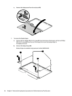
d.
Remove the webcam/microphone module from the display
(3)
.
The webcam for touch displays is available using spare part number 810961-001.
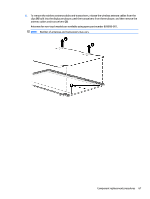
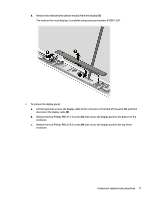
3.
To remove the display panel:
a.
Lift the tape that secures the display cable to the connector on the back of the panel
(1)
, and then
disconnect the display cable
(2)
.
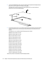
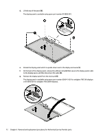
b.
Remove the two Phillips PM2.0×1.5 screws
(3)
that secure the display panel to the bottom of the
enclosure.
c.
Remove the two Phillips PM2.0×2.0 screws
(4)
that secure the display panel to the top of the
enclosure.
Component replacement procedures
71