HP Pavilion 15-bc300 Maintenance and Service Guide - Page 62
Fan assembly
 |
View all HP Pavilion 15-bc300 manuals
Add to My Manuals
Save this manual to your list of manuals |
Page 62 highlights
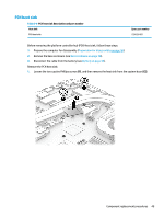
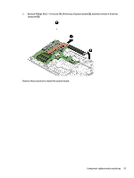
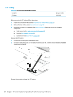
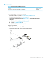
Fan assembly Table 5-11 Fan descriptions and part numbers Description Fan assembly for use in models 15-dp0000~0999 Fan assembly for use in models 15-bc300~bc399, 15-bc400~bc499, 15-bc500~bc599 Spare part number L42999-001 L18458-001 Before removing the fan assembly, follow these steps: 1. Prepare the computer for disassembly (Preparation for disassembly on page 36). 2. Remove the base enclosure (see Base enclosure on page 36). 3. Disconnect the cable from the battery (see Battery on page 38). Remove the fan assembly: 1. Disconnect the fan cables from the system board (1), and then release the display cable from the threading channel in the right fan (2). 2. Remove the four Phillips M2.0 × 4.0 screws from the fans (3), and then remove the right fan (4) and the left fan (5) from the computer. TIP: The right fan sits on top of the left fan on the shared post between the fans near the heat sink. Reverse this procedure to install the fan assembly. IMPORTANT: When replacing the fans, you must install the left fan first. 54 Chapter 5 Removal and replacement procedures for authorized service provider parts
-
 1
1 -
2
-
3
-
4
-
5
-
6
-
7
-
8
-
9
-
10
-
11
-
12
-
13
-
14
-
15
-
16
-
17
-
18
-
19
-
20
-
21
-
22
-
23
-
24
-
25
-
26
-
27
-
28
-
29
-
30
-
31
-
32
-
33
-
34
-
35
-
36
-
37
-
38
-
39
-
40
-
41
-
42
-
43
-
44
-
45
-
46
-
47
-
48
-
49
-
50
-
51
-
52
-
53
-
54
-
55
-
56
-
 57
57 -
 58
58 -
 59
59 -
 60
60 -
 61
61 -
 62
62 -
 63
63 -
 64
64 -
 65
65 -
 66
66 -
 67
67 -
68
-
69
-
70
-
71
-
72
-
73
-
74
-
75
-
76
-
77
-
78
-
79
-
80
-
81
-
82
-
83
-
84
-
85
-
86
-
87
-
88
-
89
-
90
-
91
-
92
-
93
-
94
-
95
-
96
-
97
-
98
 |
 |
