HP Pavilion Sleekbook 15-b000 HP Pavilion Sleekbook 15 Maintenance and Service - Page 75
RJ-45 cover, Remove the Phillips M screw
 |
View all HP Pavilion Sleekbook 15-b000 manuals
Add to My Manuals
Save this manual to your list of manuals |
Page 75 highlights
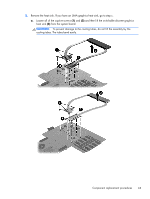
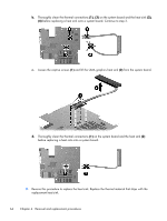
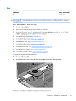
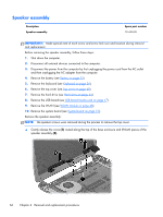
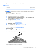
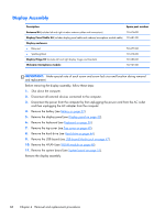
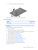
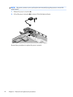
Reverse this procedure to install the speaker assembly on the base enclosure. RJ-45 cover Description RJ-45 cover Spare part number 703075-001 IMPORTANT: Make special note of each screw and screw lock size and location during removal and replacement. Before removing the RJ-45 cover, follow these steps: 1. Shut down the computer. 2. Disconnect all external devices connected to the computer. 3. Disconnect the power from the computer by first unplugging the power cord from the AC outlet and then unplugging the AC adapter from the computer. 4. Remove the battery (see Battery on page 32). 5. Remove the keyboard (see Keyboard on page 36). 6. Remove the top cover (see Top cover on page 40). 7. Remove the hard drive (see Hard drive on page 44). 8. Remove the USB board (see USB board/Audio jack on page 47). 9. Remove the WLAN (see WLAN module on page 48). 10. Remove the system board (see System board on page 51). Remove the RJ-45 cover: 1. Remove the Phillips M screw (1) for the RJ-45 cover. 2. Lift the RJ-45 assembly (2) to remove it from the base enclosure. Reverse these procedures to replace the RJ-45 assembly. Component replacement procedures 67
-
 1
1 -
2
-
3
-
4
-
5
-
6
-
7
-
8
-
9
-
10
-
11
-
12
-
13
-
14
-
15
-
16
-
17
-
18
-
19
-
20
-
21
-
22
-
23
-
24
-
25
-
26
-
27
-
28
-
29
-
30
-
31
-
32
-
33
-
34
-
35
-
36
-
37
-
38
-
39
-
40
-
41
-
42
-
43
-
44
-
45
-
46
-
47
-
48
-
49
-
50
-
51
-
52
-
53
-
54
-
55
-
56
-
57
-
58
-
59
-
60
-
61
-
62
-
63
-
64
-
65
-
66
-
67
-
68
-
69
-
 70
70 -
 71
71 -
 72
72 -
 73
73 -
 74
74 -
 75
75 -
 76
76 -
 77
77 -
 78
78 -
 79
79 -
 80
80 -
81
-
82
-
83
-
84
-
85
-
86
-
87
-
88
-
89
-
90
-
91
-
92
-
93
-
94
-
95
-
96
-
97
-
98
-
99
-
100
-
101
 |
 |