HP Pavilion Touch 14-n000 Maintenance and Service Guide - Page 64
Phillips M2.0×2.5 screw, The WLAN module tilts up.
 |
View all HP Pavilion Touch 14-n000 manuals
Add to My Manuals
Save this manual to your list of manuals |
Page 64 highlights
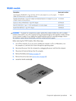
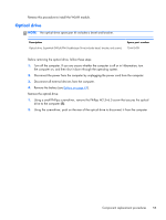
Remove the WLAN module: 1. Disconnect the WLAN antenna cables (1) from the terminals on the WLAN module. NOTE: The #1 WLAN antenna cable is connected to the WLAN module "Main" terminal. The #2 WLAN antenna cable is connected to the WLAN module "Aux" terminal. 2. Remove the Phillips M2.0×2.5 screw (2) that secures the WLAN module to the system board. (The WLAN module tilts up.) 3. Remove the WLAN module (3) by pulling the module away from the slot at an angle. NOTE: If the WLAN antennas are not connected to the terminals on the WLAN module, the protective sleeves should be installed on the antenna connectors, as shown in the following illustration. 54 Chapter 5 Removal and replacement procedures for Customer Self-Repair parts
-
 1
1 -
2
-
3
-
4
-
5
-
6
-
7
-
8
-
9
-
10
-
11
-
12
-
13
-
14
-
15
-
16
-
17
-
18
-
19
-
20
-
21
-
22
-
23
-
24
-
25
-
26
-
27
-
28
-
29
-
30
-
31
-
32
-
33
-
34
-
35
-
36
-
37
-
38
-
39
-
40
-
41
-
42
-
43
-
44
-
45
-
46
-
47
-
48
-
49
-
50
-
51
-
52
-
53
-
54
-
55
-
56
-
57
-
58
-
 59
59 -
 60
60 -
 61
61 -
 62
62 -
 63
63 -
 64
64 -
 65
65 -
 66
66 -
 67
67 -
 68
68 -
 69
69 -
70
-
71
-
72
-
73
-
74
-
75
-
76
-
77
-
78
-
79
-
80
-
81
-
82
-
83
-
84
-
85
-
86
-
87
-
88
-
89
-
90
-
91
-
92
-
93
-
94
-
95
-
96
-
97
-
98
-
99
-
100
-
101
-
102
-
103
-
104
-
105
-
106
-
107
-
108
-
109
-
110
-
111
-
112
-
113
-
114
-
115
-
116
-
117
-
118
-
119
-
120
-
121
-
122
-
123
-
124
-
125
-
126
-
127
-
128
-
129
-
130
-
131
-
132
-
133
-
134
-
135
-
136
-
137
-
138
-
139
-
140
-
141
-
142
 |
 |
Remove the WLAN module:
1.
Disconnect the WLAN antenna cables
(1)
from the terminals on the WLAN module.
NOTE:
The #1 WLAN antenna cable is connected to the WLAN module “Main” terminal.
The #2 WLAN antenna cable is connected to the WLAN module “Aux” terminal.
2.
Remove the
Phillips M2.0×2.5 screw
(2)
that secures the WLAN module to the system board.
(The WLAN module tilts up.)
3.
Remove the WLAN module
(3)
by pulling the module away from the slot at an angle.
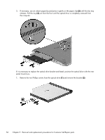
NOTE:
If the WLAN antennas are not connected to the terminals on the WLAN module, the protective
sleeves should be installed on the antenna connectors, as shown in the following illustration.
54
Chapter 5
Removal and replacement procedures for Customer Self-Repair parts