HP Pavilion Touch 14-n000 Maintenance and Service Guide - Page 93
RTC battery see, Power connector cable see
 |
View all HP Pavilion Touch 14-n000 manuals
Add to My Manuals
Save this manual to your list of manuals |
Page 93 highlights
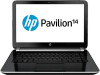
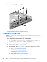
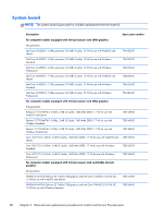
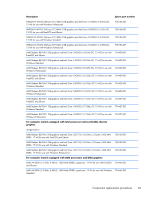
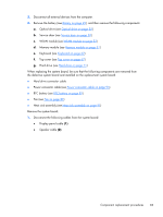
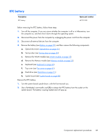
3. Disconnect all external devices from the computer. 4. Remove the battery (see Battery on page 49), and then remove the following components: a. Optical drive (see Optical drive on page 55) b. Service door (see Service door on page 50) c. WLAN module (see WLAN module on page 53) d. Memory module (see Memory module on page 51) e. Keyboard (see Keyboard on page 62) f. Top cover (see Top cover on page 67) g. Hard drive (see Hard drive on page 71) When replacing the system board, be sure that the following components are removed from the defective system board and installed on the replacement system board: ● Hard drive connector cable ● Power connector cable (see Power connector cable on page 95) ● RTC battery (see RTC battery on page 87) ● Fan (see Fan on page 89) ● Heat sink assembly (see Heat sink assembly on page 91) Remove the system board: 1. Disconnect the following cables from the system board: ● Display panel cable (1) ● Speaker cable (2) Component replacement procedures 83
-
 1
1 -
2
-
3
-
4
-
5
-
6
-
7
-
8
-
9
-
10
-
11
-
12
-
13
-
14
-
15
-
16
-
17
-
18
-
19
-
20
-
21
-
22
-
23
-
24
-
25
-
26
-
27
-
28
-
29
-
30
-
31
-
32
-
33
-
34
-
35
-
36
-
37
-
38
-
39
-
40
-
41
-
42
-
43
-
44
-
45
-
46
-
47
-
48
-
49
-
50
-
51
-
52
-
53
-
54
-
55
-
56
-
57
-
58
-
59
-
60
-
61
-
62
-
63
-
64
-
65
-
66
-
67
-
68
-
69
-
70
-
71
-
72
-
73
-
74
-
75
-
76
-
77
-
78
-
79
-
80
-
81
-
82
-
83
-
84
-
85
-
86
-
87
-
 88
88 -
 89
89 -
 90
90 -
 91
91 -
 92
92 -
 93
93 -
 94
94 -
 95
95 -
 96
96 -
 97
97 -
 98
98 -
99
-
100
-
101
-
102
-
103
-
104
-
105
-
106
-
107
-
108
-
109
-
110
-
111
-
112
-
113
-
114
-
115
-
116
-
117
-
118
-
119
-
120
-
121
-
122
-
123
-
124
-
125
-
126
-
127
-
128
-
129
-
130
-
131
-
132
-
133
-
134
-
135
-
136
-
137
-
138
-
139
-
140
-
141
-
142
 |
 |