HP Pavilion TouchSmart 15-n100 Maintenance and Service Guide - Page 107
Turn off the computer. If you are unsure whether the computer is off or in Hibernation, turn
 |
View all HP Pavilion TouchSmart 15-n100 manuals
Add to My Manuals
Save this manual to your list of manuals |
Page 107 highlights
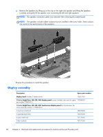
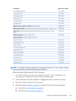
Description Spare part number In revolutionary blue finish 737172-001 In regal purple finish 737173-001 In mineral black finish 737174-001 In Goji berry finish 737175-001 In hazel berry finish 737176-001 In raspberry finish 737177-001 Webcamera/microphone module (includes adhesive) 738664-001 Display panel cable (includes webcamera/microphone module cable and two rubber screws) 732066-001 Antenna Kit (includes left and right wireless antenna cables and transceivers and 2 rubber screws) 732063-001 Display Hinge Kit (includes 2 rubber screws): 732072-001 Display enclosure (includes 2 rubber screw covers): In pearl white finish 725611-001 In sparkling black finish 725612-001 In flyer red finish 725613-001 In revolutionary blue finish 725614-001 In regal purple finish 725615-001 In aluminum metal finish 732064-001 In mineral black finish 737166-001 In Goji berry finish 737167-001 In hazel berry finish 737168-001 In raspberry finish 737169-001 NOTE: The display assembly is spared at the subcomponent level only. For more display assembly spare part information, see the individual removal subsections. Before removing the display assembly, follow these steps: 1. Turn off the computer. If you are unsure whether the computer is off or in Hibernation, turn the computer on, and then shut it down through the operating system. 2. Disconnect the power from the computer by unplugging the power cord from the computer. 3. Disconnect all external devices from the computer. 4. Remove the battery (see Battery on page 45), and then remove the following components: a. Optical drive (see Optical drive on page 50). b. Service door (see Service door on page 47). Component replacement procedures 97
-
 1
1 -
2
-
3
-
4
-
5
-
6
-
7
-
8
-
9
-
10
-
11
-
12
-
13
-
14
-
15
-
16
-
17
-
18
-
19
-
20
-
21
-
22
-
23
-
24
-
25
-
26
-
27
-
28
-
29
-
30
-
31
-
32
-
33
-
34
-
35
-
36
-
37
-
38
-
39
-
40
-
41
-
42
-
43
-
44
-
45
-
46
-
47
-
48
-
49
-
50
-
51
-
52
-
53
-
54
-
55
-
56
-
57
-
58
-
59
-
60
-
61
-
62
-
63
-
64
-
65
-
66
-
67
-
68
-
69
-
70
-
71
-
72
-
73
-
74
-
75
-
76
-
77
-
78
-
79
-
80
-
81
-
82
-
83
-
84
-
85
-
86
-
87
-
88
-
89
-
90
-
91
-
92
-
93
-
94
-
95
-
96
-
97
-
98
-
99
-
100
-
101
-
 102
102 -
 103
103 -
 104
104 -
 105
105 -
 106
106 -
 107
107 -
 108
108 -
 109
109 -
 110
110 -
 111
111 -
 112
112 -
113
-
114
-
115
-
116
-
117
-
118
-
119
-
120
-
121
-
122
-
123
-
124
-
125
-
126
-
127
-
128
-
129
-
130
-
131
-
132
-
133
-
134
-
135
-
136
-
137
-
138
-
139
-
140
-
141
 |
 |
