HP Pavilion dm1-2100 HP Pavilion dm1 Notebook PC - Maintenance and Service Gui - Page 47
CAUTION, module tilts up.
 |
View all HP Pavilion dm1-2100 manuals
Add to My Manuals
Save this manual to your list of manuals |
Page 47 highlights
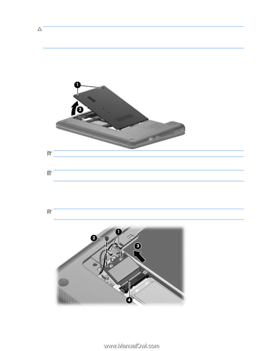
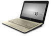
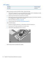
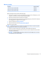
CAUTION: To prevent an unresponsive system, replace the wireless module only with a wireless module authorized for use in the computer by the governmental agency that regulates wireless devices in your country or region. If you replace the module and then receive a warning message, remove the module to restore computer functionality, and then contact technical support through Help and Support. 1. Position the computer upside down on a flat surface, with the front toward you. 2. Loosen the 2 PM2.0×6.0 captive screws (1) that secure the hard drive cover to the computer. 3. Lift the left side of the cover (2) to detach it from the computer, and remove the hard drive cover. NOTE: The hard drive cover is included in the Plastics Kit, part number 608634-001. 4. Disconnect the WLAN antenna cables (1) from the terminals on the WLAN module. NOTE: The black WLAN antenna cable is connected to the WLAN module "Main" terminal. The gray WLAN antenna cable is connected to the WLAN module "Aux" terminal. 5. Remove the PM2.0×3.5 screw (2) that secures the WLAN module to the system board. (The WLAN module tilts up.) 6. Remove the WLAN module (3) by pulling it away from the slot at an angle. NOTE: WLAN modules are designed with a notch (4) to prevent incorrect insertion of the WLAN module into the WLAN module slot. Reverse this procedure to install the WLAN module. Component replacement procedures 39
-
 1
1 -
2
-
3
-
4
-
5
-
6
-
7
-
8
-
9
-
10
-
11
-
12
-
13
-
14
-
15
-
16
-
17
-
18
-
19
-
20
-
21
-
22
-
23
-
24
-
25
-
26
-
27
-
28
-
29
-
30
-
31
-
32
-
33
-
34
-
35
-
36
-
37
-
38
-
39
-
40
-
41
-
 42
42 -
 43
43 -
 44
44 -
 45
45 -
 46
46 -
 47
47 -
 48
48 -
 49
49 -
 50
50 -
 51
51 -
 52
52 -
53
-
54
-
55
-
56
-
57
-
58
-
59
-
60
-
61
-
62
-
63
-
64
-
65
-
66
-
67
-
68
-
69
-
70
-
71
-
72
-
73
-
74
-
75
-
76
-
77
-
78
-
79
-
80
-
81
-
82
-
83
-
84
-
85
-
86
-
87
-
88
-
89
-
90
-
91
-
92
-
93
-
94
-
95
-
96
-
97
-
98
-
99
-
100
-
101
-
102
-
103
-
104
-
105
-
106
-
107
-
108
-
109
-
110
-
111
 |
 |