HP Pavilion dm1-4000 HP Pavilion dm1 Entertainment PC - Maintenance and Servic - Page 77
from the system board., Turn the system board upside down, with the right side toward you.
 |
View all HP Pavilion dm1-4000 manuals
Add to My Manuals
Save this manual to your list of manuals |
Page 77 highlights
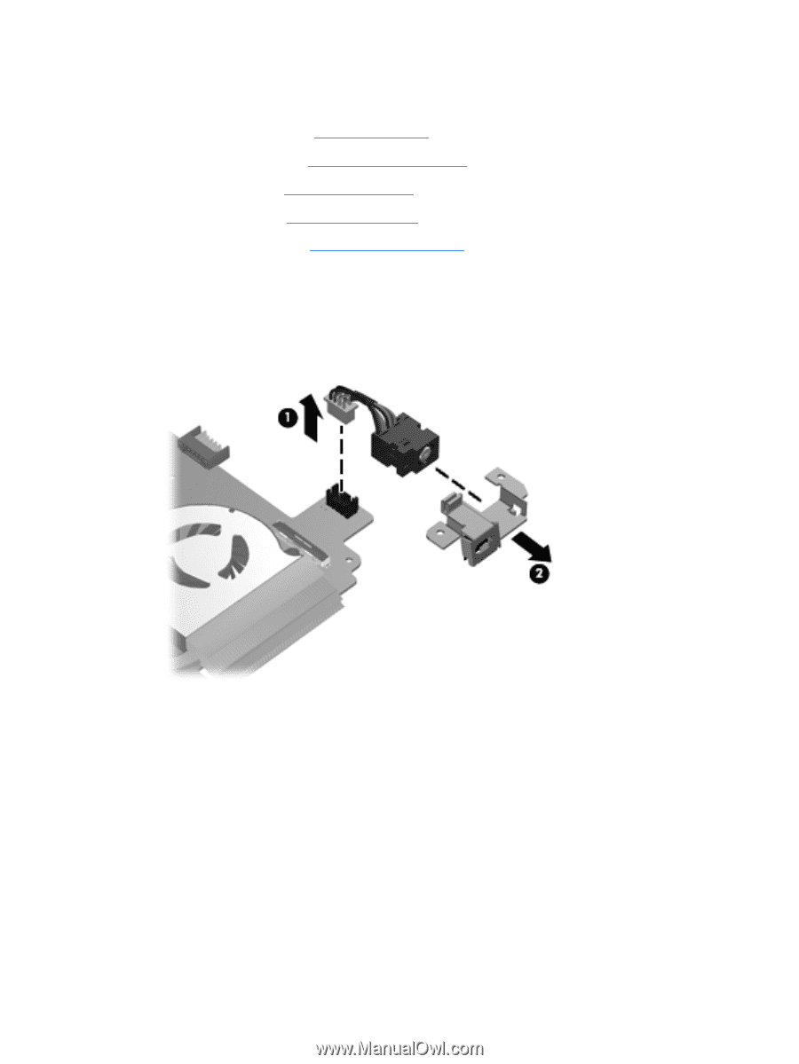
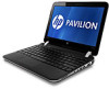
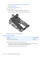
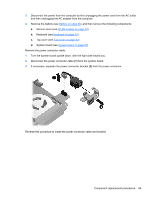
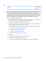
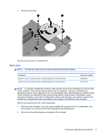
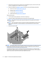
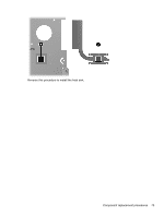
3. Disconnect the power from the computer by first unplugging the power cord from the AC outlet and then unplugging the AC adapter from the computer. 4. Remove the battery (see Battery on page 38), and then remove the following components: a. Service cover (see WLAN module on page 43) b. Keyboard (see Keyboard on page 53) c. Top cover (see Top cover on page 62) d. System board (see System board on page 67) Remove the power connector cable: 1. Turn the system board upside down, with the right side toward you. 2. Disconnect the power connector cable (1) from the system board. 3. If necessary, separate the power connector bracket (2) from the power connector. Reverse this procedure to install the power connector cable and bracket. Component replacement procedures 69
-
 1
1 -
2
-
3
-
4
-
5
-
6
-
7
-
8
-
9
-
10
-
11
-
12
-
13
-
14
-
15
-
16
-
17
-
18
-
19
-
20
-
21
-
22
-
23
-
24
-
25
-
26
-
27
-
28
-
29
-
30
-
31
-
32
-
33
-
34
-
35
-
36
-
37
-
38
-
39
-
40
-
41
-
42
-
43
-
44
-
45
-
46
-
47
-
48
-
49
-
50
-
51
-
52
-
53
-
54
-
55
-
56
-
57
-
58
-
59
-
60
-
61
-
62
-
63
-
64
-
65
-
66
-
67
-
68
-
69
-
70
-
71
-
 72
72 -
 73
73 -
 74
74 -
 75
75 -
 76
76 -
 77
77 -
 78
78 -
 79
79 -
 80
80 -
 81
81 -
 82
82 -
83
-
84
-
85
-
86
-
87
-
88
-
89
-
90
-
91
-
92
-
93
-
94
-
95
-
96
-
97
-
98
-
99
-
100
-
101
-
102
-
103
-
104
-
105
-
106
-
107
-
108
-
109
-
110
-
111
-
112
 |
 |