HP Pavilion dm4-1000 HP Pavilion dm4 Entertainment PC - Maintenance and Servic - Page 92
Due to the adhesive quality of the thermal material located between the fan/heat sink
 |
View all HP Pavilion dm4-1000 manuals
Add to My Manuals
Save this manual to your list of manuals |
Page 92 highlights
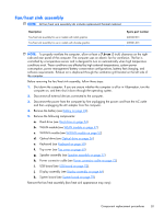
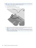
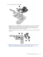
NOTE: Steps 1 through 4 apply to computers with discrete subsystem memory on the system board. Steps 5 through 7 apply to computers with UMA subsystem memory. 1. Turn the system board upside down. 2. Disconnect the fan cable from the system board. 3. Follow the sequence embossed on heat sink to loosen the six Phillips PM2.5×7.0 captive screws (1) that secure the fan/heat sink assembly to the system board. NOTE: Due to the adhesive quality of the thermal material located between the fan/heat sink assembly and system board components, it may be necessary to move the fan/heat sink assembly from side to side to detach the assembly. 82 Chapter 4 Removal and replacement procedures
-
 1
1 -
2
-
3
-
4
-
5
-
6
-
7
-
8
-
9
-
10
-
11
-
12
-
13
-
14
-
15
-
16
-
17
-
18
-
19
-
20
-
21
-
22
-
23
-
24
-
25
-
26
-
27
-
28
-
29
-
30
-
31
-
32
-
33
-
34
-
35
-
36
-
37
-
38
-
39
-
40
-
41
-
42
-
43
-
44
-
45
-
46
-
47
-
48
-
49
-
50
-
51
-
52
-
53
-
54
-
55
-
56
-
57
-
58
-
59
-
60
-
61
-
62
-
63
-
64
-
65
-
66
-
67
-
68
-
69
-
70
-
71
-
72
-
73
-
74
-
75
-
76
-
77
-
78
-
79
-
80
-
81
-
82
-
83
-
84
-
85
-
86
-
 87
87 -
 88
88 -
 89
89 -
 90
90 -
 91
91 -
 92
92 -
 93
93 -
 94
94 -
 95
95 -
 96
96 -
 97
97 -
98
-
99
-
100
-
101
-
102
-
103
-
104
-
105
-
106
-
107
-
108
-
109
-
110
-
111
-
112
-
113
-
114
-
115
-
116
-
117
-
118
-
119
-
120
-
121
-
122
-
123
-
124
-
125
-
126
-
127
-
128
-
129
 |
 |
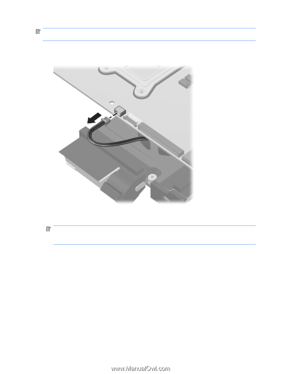
NOTE:
Steps 1 through 4 apply to computers with discrete subsystem memory on the system board.
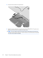
Steps 5 through 7 apply to computers with UMA subsystem memory.
1.
Turn the system board upside down.
2.
Disconnect the fan cable from the system board.
3.
Follow the sequence embossed on heat sink to loosen the six Phillips PM2.5×7.0 captive screws
(1)
that secure the fan/heat sink assembly to the system board.
NOTE:
Due to the adhesive quality of the thermal material located between the fan/heat sink
assembly and system board components, it may be necessary to move the fan/heat sink assembly
from side to side to detach the assembly.
82
Chapter 4
Removal and replacement procedures