HP Pavilion dm4-1000 HP Pavilion dm4 Entertainment PC - Maintenance and Servic - Page 93
The following illustration shows the locations for thermal material on systems with discrete graphics
 |
View all HP Pavilion dm4-1000 manuals
Add to My Manuals
Save this manual to your list of manuals |
Page 93 highlights
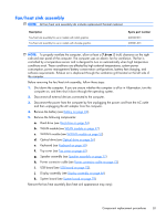
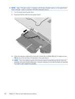
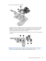
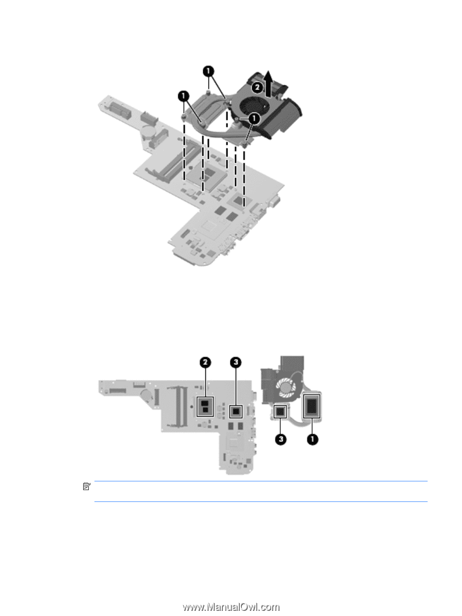
4. Remove the fan/heat sink assembly (2). The thermal material must be thoroughly cleaned from the surfaces of the fan/heat sink assembly (1), (3) and the processor (2) and graphics processor (3) on the system board each time the fan/heat sink assembly is removed. Thermal pads and thermal paste must be installed on all surfaces before the fan/heat sink assembly is reinstalled. The following illustration shows the locations for thermal material on systems with discrete graphics subsystems. NOTE: Steps 5 through 7 apply to computers with UMA subsystem memory on the system board. Steps 1 through 4 apply to computers with discrete subsystem memory. Component replacement procedures 83
-
 1
1 -
2
-
3
-
4
-
5
-
6
-
7
-
8
-
9
-
10
-
11
-
12
-
13
-
14
-
15
-
16
-
17
-
18
-
19
-
20
-
21
-
22
-
23
-
24
-
25
-
26
-
27
-
28
-
29
-
30
-
31
-
32
-
33
-
34
-
35
-
36
-
37
-
38
-
39
-
40
-
41
-
42
-
43
-
44
-
45
-
46
-
47
-
48
-
49
-
50
-
51
-
52
-
53
-
54
-
55
-
56
-
57
-
58
-
59
-
60
-
61
-
62
-
63
-
64
-
65
-
66
-
67
-
68
-
69
-
70
-
71
-
72
-
73
-
74
-
75
-
76
-
77
-
78
-
79
-
80
-
81
-
82
-
83
-
84
-
85
-
86
-
87
-
 88
88 -
 89
89 -
 90
90 -
 91
91 -
 92
92 -
 93
93 -
 94
94 -
 95
95 -
 96
96 -
 97
97 -
 98
98 -
99
-
100
-
101
-
102
-
103
-
104
-
105
-
106
-
107
-
108
-
109
-
110
-
111
-
112
-
113
-
114
-
115
-
116
-
117
-
118
-
119
-
120
-
121
-
122
-
123
-
124
-
125
-
126
-
127
-
128
-
129
 |
 |
4.
Remove the fan/heat sink assembly
(2)
.
The thermal material must be thoroughly cleaned from the surfaces of the fan/heat sink assembly
(1)
,
(3)
and the processor
(2)
and graphics processor
(3)
on the system board each time the
fan/heat sink assembly is removed. Thermal pads and thermal paste must be installed on all
surfaces before the fan/heat sink assembly is reinstalled.
The following illustration shows the locations for thermal material on systems with discrete graphics
subsystems.
NOTE:
Steps 5 through 7 apply to computers with UMA subsystem memory on the system
board. Steps 1 through 4 apply to computers with discrete subsystem memory.
Component replacement procedures
83