HP Pavilion dv4200 HP Pavilion dv4000 Notebook PC and Compaq Presario V4000 No - Page 142
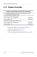
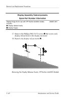
Display Assembly Subcomponents, Spare Part Number Information
 |
View all HP Pavilion dv4200 manuals
Add to My Manuals
Save this manual to your list of manuals |
Page 142 highlights
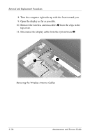
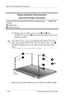
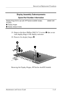
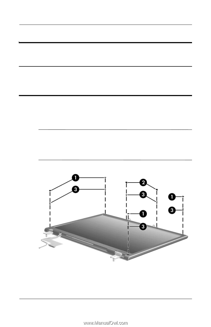
Removal and Replacement Procedures Display Assembly Subcomponents Spare Part Number Information Display Plastics Kit for use with HP Pavilion dv4000 models, includes: ■ Display bezel ■ Display enclosure 403919-001 14. Remove the six rubber screw covers 1 and 2 and six PM2.5×7.0 screws 3 that secure the display bezel to the display assembly. ✎ The rubber screw covers are included in the Display Screw Kit, spare part number 403923-001. The four taller screw covers 1 should be installed in the screw holes on the top edge of the bezel. Removing the Display Bezel Screws, HP Pavilion dv4000 Models 5-38 Maintenance and Service Guide
-
 1
1 -
2
-
3
-
4
-
5
-
6
-
7
-
8
-
9
-
10
-
11
-
12
-
13
-
14
-
15
-
16
-
17
-
18
-
19
-
20
-
21
-
22
-
23
-
24
-
25
-
26
-
27
-
28
-
29
-
30
-
31
-
32
-
33
-
34
-
35
-
36
-
37
-
38
-
39
-
40
-
41
-
42
-
43
-
44
-
45
-
46
-
47
-
48
-
49
-
50
-
51
-
52
-
53
-
54
-
55
-
56
-
57
-
58
-
59
-
60
-
61
-
62
-
63
-
64
-
65
-
66
-
67
-
68
-
69
-
70
-
71
-
72
-
73
-
74
-
75
-
76
-
77
-
78
-
79
-
80
-
81
-
82
-
83
-
84
-
85
-
86
-
87
-
88
-
89
-
90
-
91
-
92
-
93
-
94
-
95
-
96
-
97
-
98
-
99
-
100
-
101
-
102
-
103
-
104
-
105
-
106
-
107
-
108
-
109
-
110
-
111
-
112
-
113
-
114
-
115
-
116
-
117
-
118
-
119
-
120
-
121
-
122
-
123
-
124
-
125
-
126
-
127
-
128
-
129
-
130
-
131
-
132
-
133
-
134
-
135
-
136
-
 137
137 -
 138
138 -
 139
139 -
 140
140 -
 141
141 -
 142
142 -
 143
143 -
 144
144 -
 145
145 -
 146
146 -
 147
147 -
148
-
149
-
150
-
151
-
152
-
153
-
154
-
155
-
156
-
157
-
158
-
159
-
160
-
161
-
162
-
163
-
164
-
165
-
166
-
167
-
168
-
169
-
170
-
171
-
172
-
173
-
174
-
175
-
176
-
177
-
178
-
179
-
180
-
181
-
182
-
183
-
184
-
185
-
186
-
187
-
188
-
189
-
190
-
191
-
192
-
193
-
194
-
195
-
196
-
197
-
198
-
199
-
200
-
201
-
202
-
203
-
204
-
205
-
206
-
207
-
208
-
209
-
210
-
211
-
212
-
213
-
214
-
215
-
216
-
217
-
218
-
219
-
220
-
221
-
222
-
223
-
224
-
225
-
226
-
227
-
228
-
229
-
230
-
231
-
232
-
233
-
234
-
235
-
236
-
237
-
238
-
239
-
240
-
241
-
242
-
243
-
244
-
245
-
246
-
247
-
248
-
249
-
250
-
251
-
252
-
253
-
254
-
255
-
256
-
257
-
258
-
259
-
260
-
261
-
262
-
263
-
264
-
265
-
266
 |
 |
5–38
Maintenance and Service Guide
Removal and Replacement Procedures
14. Remove the six rubber screw covers
1
and
2
and
six PM2.5×7.0 screws
3
that secure the display bezel to the
display assembly.
✎
The rubber screw covers are included in the Display Screw Kit,
spare part number 403923-001. The four taller screw covers
1
should be installed in the screw holes on the top edge of the
bezel.
Removing the Display Bezel Screws, HP Pavilion dv4000 Models
Display Assembly Subcomponents
Spare Part Number Information
Display Plastics Kit for use with HP Pavilion dv4000 models,
includes:
■
Display bezel
■
Display enclosure
403919-001