HP Pavilion dv6-2000 HP Pavilion dv6 Entertainment PC - Maintenance and Servic - Page 49
Memory module, that secure the memory module compartment cover
 |
View all HP Pavilion dv6-2000 manuals
Add to My Manuals
Save this manual to your list of manuals |
Page 49 highlights
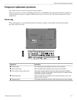
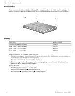
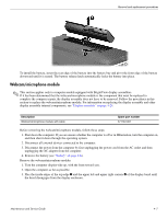
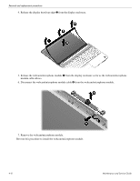
Removal and replacement procedures Reverse this procedure to reassemble and install the optical drive. Memory module Description 4096-MB, 1066 MHz DDR-3 DIMM 2048-MB, 1066 MHz DDR-3 DIMM 1024-MB, 1066 MHz DDR-3 DIMM Spare part number 579156-001 579155-001 579154-001 Before removing the memory module, follow these steps: 1. Shut down the computer. If you are unsure whether the computer is off or in Hibernation, turn the computer on, and then shut it down through the operating system. 2. Disconnect all external devices connected to the computer. 3. Disconnect the power from the computer by first unplugging the power cord from the AC outlet and then unplugging the AC adapter from the computer. 4. Remove the battery (see "Battery" on page 4-6). Remove the memory module: 1. Position the computer with the front toward you. 2. Remove the single screw that secures the optical drive to the computer (see "Optical drive" on page 4-9). 3. Loosen the three Phillips PM2.5×14.0 captive screws 1 that secure the memory module compartment cover to the computer. 4. Lift the rear edge 2 of the cover, swing it up and to the front, and remove the cover 3. The memory module compartment cover is included in the Plastics Kit, spare part number 579162-001. 4-10 Maintenance and Service Guide
-
 1
1 -
2
-
3
-
4
-
5
-
6
-
7
-
8
-
9
-
10
-
11
-
12
-
13
-
14
-
15
-
16
-
17
-
18
-
19
-
20
-
21
-
22
-
23
-
24
-
25
-
26
-
27
-
28
-
29
-
30
-
31
-
32
-
33
-
34
-
35
-
36
-
37
-
38
-
39
-
40
-
41
-
42
-
43
-
 44
44 -
 45
45 -
 46
46 -
 47
47 -
 48
48 -
 49
49 -
 50
50 -
 51
51 -
 52
52 -
 53
53 -
 54
54 -
55
-
56
-
57
-
58
-
59
-
60
-
61
-
62
-
63
-
64
-
65
-
66
-
67
-
68
-
69
-
70
-
71
-
72
-
73
-
74
-
75
-
76
-
77
-
78
-
79
-
80
-
81
-
82
-
83
-
84
-
85
-
86
-
87
-
88
-
89
-
90
-
91
-
92
-
93
-
94
-
95
-
96
-
97
-
98
-
99
-
100
-
101
-
102
-
103
-
104
-
105
-
106
-
107
-
108
-
109
-
110
-
111
-
112
-
113
-
114
-
115
-
116
-
117
-
118
-
119
-
120
-
121
-
122
-
123
-
124
-
125
-
126
-
127
-
128
-
129
-
130
-
131
-
132
-
133
-
134
-
135
-
136
-
137
 |
 |
