HP Pavilion dv6-3200 HP Pavilion dv6 Entertainment PC - Maintenance and Servic - Page 76
The screw covers are included in the Display, Remove the Mylar screw covers
 |
View all HP Pavilion dv6-3200 manuals
Add to My Manuals
Save this manual to your list of manuals |
Page 76 highlights
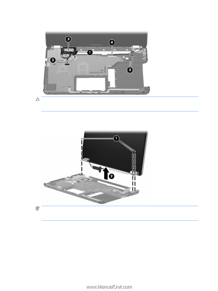
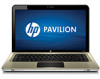
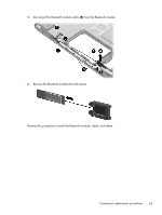
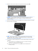
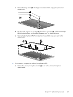
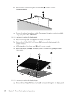
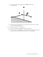
5. Release the wireless antenna cables from the clips built into the base enclosure (5). CAUTION: Support the display assembly when removing the following screws. Failure to support the display assembly can result in damage to the display assembly and other computer components. 6. Remove the three Phillips PM2.5×7.0 screws (1) that secure the display assembly to the computer. 7. Remove the display assembly (2). NOTE: Steps 8 through 12 apply to computer models equipped with traditional display assemblies. Refer to steps 13 through 17 for disassembly information for computer models equipped with the TouchScreen display assembly. 8. If it is necessary to replace the display bezel or any of the traditional display assembly internal components: a. Remove the Mylar screw covers (1). The screw covers are included in the Display Miscellaneous Kit, spare part number 603659-001. b. Remove the two Phillips PM2.5×7.0 screws (2) that secure the display bezel to the display assembly. 66 Chapter 4 Removal and replacement procedures
-
 1
1 -
2
-
3
-
4
-
5
-
6
-
7
-
8
-
9
-
10
-
11
-
12
-
13
-
14
-
15
-
16
-
17
-
18
-
19
-
20
-
21
-
22
-
23
-
24
-
25
-
26
-
27
-
28
-
29
-
30
-
31
-
32
-
33
-
34
-
35
-
36
-
37
-
38
-
39
-
40
-
41
-
42
-
43
-
44
-
45
-
46
-
47
-
48
-
49
-
50
-
51
-
52
-
53
-
54
-
55
-
56
-
57
-
58
-
59
-
60
-
61
-
62
-
63
-
64
-
65
-
66
-
67
-
68
-
69
-
70
-
 71
71 -
 72
72 -
 73
73 -
 74
74 -
 75
75 -
 76
76 -
 77
77 -
 78
78 -
 79
79 -
 80
80 -
 81
81 -
82
-
83
-
84
-
85
-
86
-
87
-
88
-
89
-
90
-
91
-
92
-
93
-
94
-
95
-
96
-
97
-
98
-
99
-
100
-
101
-
102
-
103
-
104
-
105
-
106
-
107
-
108
-
109
-
110
-
111
-
112
-
113
-
114
-
115
-
116
-
117
-
118
-
119
-
120
-
121
-
122
-
123
-
124
-
125
-
126
-
127
-
128
-
129
-
130
 |
 |