HP Pavilion dv9600 HP Pavilion dv9500, dv9600, and dv9700 Entertainment PCs - - Page 101
from the base enclosure as far as the rear USB board cable allows., Release the rear USB board
 |
View all HP Pavilion dv9600 manuals
Add to My Manuals
Save this manual to your list of manuals |
Page 101 highlights
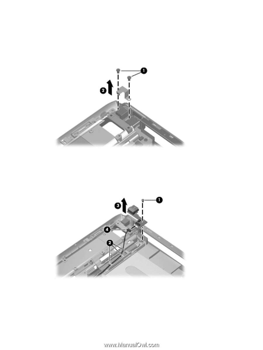
Remove the rear USB board: 1. Remove the two silver Phillips PM2.5×5.0 screws (1) that secure the power connector bracket to the computer. 2. Remove the power connector bracket (2). The power connector bracket is available using spare part number 432985-001. 3. Remove the silver Phillips PM2.5×5.0 screw (1) that secures the rear USB board to the base enclosure. 4. Remove the rear USB board cable from the clips (2) built into the base enclosure. 5. Release the rear USB board (3) from the base enclosure as far as the rear USB board cable allows. 6. Disconnect the rear USB board cable (4) from the rear USB board. 7. Remove the rear USB board. Reverse this procedure to install the rear USB board. Component replacement procedures 91
-
 1
1 -
2
-
3
-
4
-
5
-
6
-
7
-
8
-
9
-
10
-
11
-
12
-
13
-
14
-
15
-
16
-
17
-
18
-
19
-
20
-
21
-
22
-
23
-
24
-
25
-
26
-
27
-
28
-
29
-
30
-
31
-
32
-
33
-
34
-
35
-
36
-
37
-
38
-
39
-
40
-
41
-
42
-
43
-
44
-
45
-
46
-
47
-
48
-
49
-
50
-
51
-
52
-
53
-
54
-
55
-
56
-
57
-
58
-
59
-
60
-
61
-
62
-
63
-
64
-
65
-
66
-
67
-
68
-
69
-
70
-
71
-
72
-
73
-
74
-
75
-
76
-
77
-
78
-
79
-
80
-
81
-
82
-
83
-
84
-
85
-
86
-
87
-
88
-
89
-
90
-
91
-
92
-
93
-
94
-
95
-
 96
96 -
 97
97 -
 98
98 -
 99
99 -
 100
100 -
 101
101 -
 102
102 -
 103
103 -
 104
104 -
 105
105 -
 106
106 -
107
-
108
-
109
-
110
-
111
-
112
-
113
-
114
-
115
-
116
-
117
-
118
-
119
-
120
-
121
-
122
-
123
-
124
-
125
-
126
-
127
-
128
-
129
-
130
-
131
-
132
-
133
-
134
-
135
-
136
-
137
-
138
-
139
-
140
-
141
-
142
-
143
-
144
-
145
-
146
-
147
-
148
-
149
-
150
-
151
-
152
-
153
-
154
-
155
-
156
-
157
-
158
-
159
-
160
-
161
-
162
-
163
-
164
-
165
-
166
-
167
-
168
-
169
-
170
-
171
-
172
-
173
-
174
-
175
-
176
-
177
 |
 |
Remove the rear USB board:
1.
Remove the two silver Phillips PM2.5×5.0 screws
(1)
that secure the power connector bracket to
the computer.
2.
Remove the power connector bracket
(2)
. The power connector bracket is available using spare
part number 432985-001.
3.
Remove the silver Phillips PM2.5×5.0 screw
(1)
that secures the rear USB board to the base
enclosure.
4.
Remove the rear USB board cable from the clips
(2)
built into the base enclosure.
5.
Release the rear USB board
(3)
from the base enclosure as far as the rear USB board cable allows.
6.
Disconnect the rear USB board cable
(4)
from the rear USB board.
7.
Remove the rear USB board.
Reverse this procedure to install the rear USB board.
Component replacement procedures
91