HP Pavilion dv9600 HP Pavilion dv9500, dv9600, and dv9700 Entertainment PCs - - Page 110
Disconnect the fan cable, Turn the system board upside down
 |
View all HP Pavilion dv9600 manuals
Add to My Manuals
Save this manual to your list of manuals |
Page 110 highlights
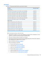
i. Audio board (see Audio board on page 97) j. Front USB board (see Front USB board on page 84) k. Top cover trim (see Top cover trim on page 87) l. System board (see System board on page 92) Remove the fan/heat assembly: 1. Turn the system board upside down, with the expansion port 3 and external monitor port toward you. 2. Disconnect the fan cable (1) from the system board. 3. Loosen the three Phillips PM2.5×5.0 captive screws (2) that secure the fan/heat sink assembly to the system board. 100 Chapter 4 Removal and replacement procedures
-
 1
1 -
2
-
3
-
4
-
5
-
6
-
7
-
8
-
9
-
10
-
11
-
12
-
13
-
14
-
15
-
16
-
17
-
18
-
19
-
20
-
21
-
22
-
23
-
24
-
25
-
26
-
27
-
28
-
29
-
30
-
31
-
32
-
33
-
34
-
35
-
36
-
37
-
38
-
39
-
40
-
41
-
42
-
43
-
44
-
45
-
46
-
47
-
48
-
49
-
50
-
51
-
52
-
53
-
54
-
55
-
56
-
57
-
58
-
59
-
60
-
61
-
62
-
63
-
64
-
65
-
66
-
67
-
68
-
69
-
70
-
71
-
72
-
73
-
74
-
75
-
76
-
77
-
78
-
79
-
80
-
81
-
82
-
83
-
84
-
85
-
86
-
87
-
88
-
89
-
90
-
91
-
92
-
93
-
94
-
95
-
96
-
97
-
98
-
99
-
100
-
101
-
102
-
103
-
104
-
 105
105 -
 106
106 -
 107
107 -
 108
108 -
 109
109 -
 110
110 -
 111
111 -
 112
112 -
 113
113 -
 114
114 -
 115
115 -
116
-
117
-
118
-
119
-
120
-
121
-
122
-
123
-
124
-
125
-
126
-
127
-
128
-
129
-
130
-
131
-
132
-
133
-
134
-
135
-
136
-
137
-
138
-
139
-
140
-
141
-
142
-
143
-
144
-
145
-
146
-
147
-
148
-
149
-
150
-
151
-
152
-
153
-
154
-
155
-
156
-
157
-
158
-
159
-
160
-
161
-
162
-
163
-
164
-
165
-
166
-
167
-
168
-
169
-
170
-
171
-
172
-
173
-
174
-
175
-
176
-
177
 |
 |

i.
Audio board (see
Audio board
on page
97
)
j.
Front USB board (see
Front USB board
on page
84
)
k.
Top cover trim (see
Top cover trim
on page
87
)
l.
System board (see
System board
on page
92
)
Remove the fan/heat assembly:
1.
Turn the system board upside down, with the expansion port 3 and external monitor port toward
you.
2.
Disconnect the fan cable
(1)
from the system board.
3.
Loosen the three Phillips PM2.5×5.0 captive screws
(2)
that secure the fan/heat sink assembly to
the system board.
100
Chapter 4
Removal and replacement procedures