HP Pavilion dx6500 HP Pavilion dx6500 Entertainment PC - Maintenance and Servi - Page 54
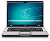
WLAN module, WLAN module middle terminal.
 |
View all HP Pavilion dx6500 manuals
Add to My Manuals
Save this manual to your list of manuals |
Page 54 highlights
WLAN module Description Intel 802.11a/g/n WLAN module Intel 802.11a/b/g WLAN module Spare part number 441086-001 451861-001 Before removing the WLAN module, follow these steps: 1. Shut down the computer. If you are unsure whether the computer is off or in Hibernation, turn the computer on, and then shut it down through the operating system. 2. Disconnect all external devices connected to the computer. 3. Disconnect the power from the computer by first unplugging the power cord from the AC outlet and then unplugging the AC adapter from the computer. 4. Remove the battery (see Battery on page 36). 5. Remove the memory/WLAN module compartment cover (see Memory module on page 43). Remove the WLAN module: 1. Disconnect the two WLAN antenna cables (1) from the WLAN module. NOTE: The black WLAN antenna cable is connected to the WLAN module "Main" terminal. The white WLAN antenna cable is connected to the WLAN module "Aux" terminal. NOTE: Computer models equipped with an 802.11a/g/n WLAN module will have an additional wireless antenna cable (2), yellow in color. Disconnect the yellow WLAN antenna cable from the WLAN module middle terminal. 2. Remove the two Phillips PM2.0×4.0 screws (3) that secure the WLAN module to the computer. (The edge of the module opposite the slot rises away from the computer.) 3. Remove the WLAN module (4) by pulling it away from the slot at an angle. NOTE: WLAN modules are designed with a notch (5) to prevent incorrect installation into the WLAN module slot. 46 Chapter 4 Removal and replacement procedures
-
 1
1 -
2
-
3
-
4
-
5
-
6
-
7
-
8
-
9
-
10
-
11
-
12
-
13
-
14
-
15
-
16
-
17
-
18
-
19
-
20
-
21
-
22
-
23
-
24
-
25
-
26
-
27
-
28
-
29
-
30
-
31
-
32
-
33
-
34
-
35
-
36
-
37
-
38
-
39
-
40
-
41
-
42
-
43
-
44
-
45
-
46
-
47
-
48
-
 49
49 -
 50
50 -
 51
51 -
 52
52 -
 53
53 -
 54
54 -
 55
55 -
 56
56 -
 57
57 -
 58
58 -
 59
59 -
60
-
61
-
62
-
63
-
64
-
65
-
66
-
67
-
68
-
69
-
70
-
71
-
72
-
73
-
74
-
75
-
76
-
77
-
78
-
79
-
80
-
81
-
82
-
83
-
84
-
85
-
86
-
87
-
88
-
89
-
90
-
91
-
92
-
93
-
94
-
95
-
96
-
97
-
98
-
99
-
100
-
101
-
102
-
103
-
104
-
105
-
106
-
107
-
108
-
109
-
110
-
111
-
112
-
113
-
114
-
115
-
116
-
117
-
118
-
119
-
120
-
121
-
122
-
123
-
124
-
125
-
126
-
127
-
128
-
129
-
130
-
131
-
132
-
133
-
134
-
135
-
136
-
137
-
138
-
139
-
140
-
141
-
142
 |
 |
