HP Presario 1900 Model XL1-XL165-Maintenance & Service Guide Presario 1900 - Page 52
Removing the, 3 inch, Display Panel, Assembly
 |
View all HP Presario 1900 manuals
Add to My Manuals
Save this manual to your list of manuals |
Page 52 highlights
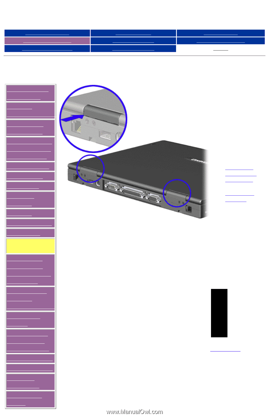
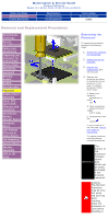
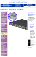
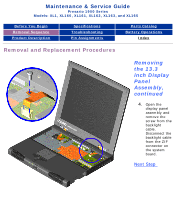
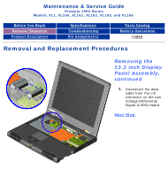
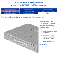
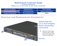
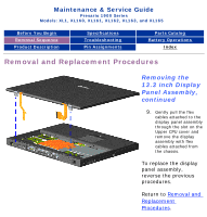
Maintenance & Service Guide Presario 1900 Series Models: XL1, XL160, XL161, XL162, XL163, and XL165 Before You Begin Removal Sequence Product Description Specifications Troubleshooting Pin Assignments Parts Catalog Battery Operations Index Removal and Replacement Procedures Electrostatic Discharge Service Considerations Cables and Connectors Preparing the Computer for Disassembly Battery Pack Hard Drive Keyboard Memory Module Modem Heatspreader Processor Display Panel Assembly Upper CPU Cover with Palmrest and TouchPad Hard Drive/ Battery Charger Board Converter Board Low Voltage Differential Signal Board Fan Assembly System Board Speaker Assembly DVD or CD Drive Removing the 13.3 inch Display Panel Assembly To remove the 13.3 inch display panel assembly, complete the following steps: 1. Prepare the computer for disassembly. 2. Remove the keyboard. 3. Close the display panel assembly to access the hinge covers from the rear of the unit. Using tweezers, gently lift from the bottom edge of the hinge covers. Lift the hinge covers off the unit. Use a pair of tweezers to properly NOTE: remove the display hinges from the unit. Next Step
-
 1
1 -
2
-
3
-
4
-
5
-
6
-
7
-
8
-
9
-
10
-
11
-
12
-
13
-
14
-
15
-
16
-
17
-
18
-
19
-
20
-
21
-
22
-
23
-
24
-
25
-
26
-
27
-
28
-
29
-
30
-
31
-
32
-
33
-
34
-
35
-
36
-
37
-
38
-
39
-
40
-
41
-
42
-
43
-
44
-
45
-
46
-
 47
47 -
 48
48 -
 49
49 -
 50
50 -
 51
51 -
 52
52 -
 53
53 -
 54
54 -
 55
55 -
 56
56 -
 57
57 -
58
-
59
-
60
-
61
-
62
-
63
-
64
-
65
-
66
-
67
-
68
-
69
-
70
-
71
-
72
-
73
-
74
-
75
-
76
-
77
-
78
-
79
-
80
-
81
-
82
 |
 |