HP Presario B1200 Compaq Presario B1200 Notebook PC - Maintenance and Service - Page 62
Display assembly, Remove the Phillips PM2.5×7.0 screw
 |
View all HP Presario B1200 manuals
Add to My Manuals
Save this manual to your list of manuals |
Page 62 highlights
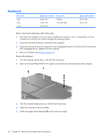
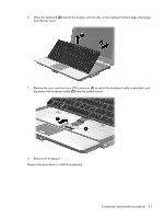
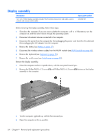
Display assembly Description 12.1-inch, WXGA display assembly (includes WLAN antenna transceivers and cables, camera module, and camera module cable) Spare part number 454003-001 Before removing the display assembly, follow these steps: 1. Shut down the computer. If you are unsure whether the computer is off or in Hibernation, turn the computer on, and then shut it down through the operating system. 2. Disconnect all external devices connected to the computer. 3. Disconnect the power from the computer by first unplugging the power cord from the AC outlet and then unplugging the AC adapter from the computer. 4. Remove the battery (see Battery on page 37). 5. Disconnect the wireless antenna cables from the WLAN module (see WLAN module on page 45). 6. Remove the keyboard (see Keyboard on page 50). 7. Remove the switch cover (see Switch cover on page 52). Remove the display assembly: 1. Close the computer and turn it upside down, with the rear panel toward you. 2. Remove the Phillips PM2.5×7.0 screw (1) and Phillips PM2.5×5.0 screw (2) that secure the display assembly to the computer. 3. Turn the computer right-side up, with the front toward you. 4. Open the computer as far as possible. 54 Chapter 4 Removal and replacement procedures
-
 1
1 -
2
-
3
-
4
-
5
-
6
-
7
-
8
-
9
-
10
-
11
-
12
-
13
-
14
-
15
-
16
-
17
-
18
-
19
-
20
-
21
-
22
-
23
-
24
-
25
-
26
-
27
-
28
-
29
-
30
-
31
-
32
-
33
-
34
-
35
-
36
-
37
-
38
-
39
-
40
-
41
-
42
-
43
-
44
-
45
-
46
-
47
-
48
-
49
-
50
-
51
-
52
-
53
-
54
-
55
-
56
-
 57
57 -
 58
58 -
 59
59 -
 60
60 -
 61
61 -
 62
62 -
 63
63 -
 64
64 -
 65
65 -
 66
66 -
 67
67 -
68
-
69
-
70
-
71
-
72
-
73
-
74
-
75
-
76
-
77
-
78
-
79
-
80
-
81
-
82
-
83
-
84
-
85
-
86
-
87
-
88
-
89
-
90
-
91
-
92
-
93
-
94
-
95
-
96
-
97
-
98
-
99
-
100
-
101
-
102
-
103
-
104
-
105
-
106
-
107
-
108
-
109
-
110
-
111
-
112
-
113
-
114
-
115
-
116
-
117
-
118
-
119
-
120
-
121
-
122
-
123
-
124
-
125
-
126
-
127
-
128
-
129
-
130
-
131
-
132
-
133
-
134
-
135
-
136
-
137
-
138
-
139
-
140
-
141
-
142
-
143
-
144
-
145
-
146
 |
 |