HP Presario B1200 Compaq Presario B1200 Notebook PC - Maintenance and Service - Page 81
Modem module, Cable Kit, on Battery, Hard drive, Optical drive, Keyboard, Switch cover
 |
View all HP Presario B1200 manuals
Add to My Manuals
Save this manual to your list of manuals |
Page 81 highlights
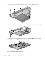
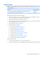
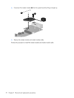
Modem module NOTE: The modem module spare part kits doe not include a modem module cable. The modem module cable is included in the Cables Kit, spare part number 454008-001. See Cable Kit on page 21 for more Cable Kit information. Description For use in all countries and regions except Japan and Asia Pacific countries and regions For use only in Japan and Asia Pacific countries and regions Spare part number 451403-001 449139-001 Before removing the modem module, follow these steps: 1. Shut down the computer. If you are unsure whether the computer is off or in Hibernation, turn the computer on, and then shut it down through the operating system. 2. Disconnect all external devices connected to the computer. 3. Disconnect the power from the computer by first unplugging the power cord from the AC outlet and then unplugging the AC adapter from the computer. 4. Remove the battery (see Battery on page 37). 5. Remove the following components: a. Hard drive (see Hard drive on page 41) b. Optical drive (see Optical drive on page 48) c. Keyboard (see Keyboard on page 50) d. Switch cover (see Switch cover on page 52) e. Display assembly (see Display assembly on page 54) f. Top cover (see Top cover on page 59) g. Bluetooth module (see Bluetooth module on page 65) h. System board (see System board on page 69) Remove the modem module: 1. Turn the system board upside down, with the rear edge toward you. 2. Remove the two Phillips PM2.5×4.0 screws (1) that secure the modem module to the system board. Component replacement procedures 73
-
 1
1 -
2
-
3
-
4
-
5
-
6
-
7
-
8
-
9
-
10
-
11
-
12
-
13
-
14
-
15
-
16
-
17
-
18
-
19
-
20
-
21
-
22
-
23
-
24
-
25
-
26
-
27
-
28
-
29
-
30
-
31
-
32
-
33
-
34
-
35
-
36
-
37
-
38
-
39
-
40
-
41
-
42
-
43
-
44
-
45
-
46
-
47
-
48
-
49
-
50
-
51
-
52
-
53
-
54
-
55
-
56
-
57
-
58
-
59
-
60
-
61
-
62
-
63
-
64
-
65
-
66
-
67
-
68
-
69
-
70
-
71
-
72
-
73
-
74
-
75
-
 76
76 -
 77
77 -
 78
78 -
 79
79 -
 80
80 -
 81
81 -
 82
82 -
 83
83 -
 84
84 -
 85
85 -
 86
86 -
87
-
88
-
89
-
90
-
91
-
92
-
93
-
94
-
95
-
96
-
97
-
98
-
99
-
100
-
101
-
102
-
103
-
104
-
105
-
106
-
107
-
108
-
109
-
110
-
111
-
112
-
113
-
114
-
115
-
116
-
117
-
118
-
119
-
120
-
121
-
122
-
123
-
124
-
125
-
126
-
127
-
128
-
129
-
130
-
131
-
132
-
133
-
134
-
135
-
136
-
137
-
138
-
139
-
140
-
141
-
142
-
143
-
144
-
145
-
146
 |
 |