HP Presario CQ58-a00 HP 2000 Notebook PC Compaq Presario CQ58 Notebook PC - Ma - Page 95
Processor, Speakers see
 |
View all HP Presario CQ58-a00 manuals
Add to My Manuals
Save this manual to your list of manuals |
Page 95 highlights
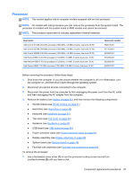
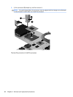
Processor NOTE: This section applies only to computer models equipped with an Intel processor. NOTE: On models with Intel processors you can remove the processor from the system board. The processor is included with the system board in AMD models and cannot be removed. NOTE: The processor spare part kit includes replacement thermal materials. Description Intel Core i3-3110M 2.40-GHz processor (1600-MHz, 3.0-MB L3 cache, dual core, 35 W) Intel Core i3-2370M 2.40-GHz processor (1333-MHz, 3.0-MB L3 cache, dual core, 35 W) Intel Core i3-2350M 2.30-GHz processor (1333-MHz, 3.0-MB L3 cache, dual core, 35 W) Intel Pentium B970 2.30-GHz processor (1333-MHz, 2.0-MB L3 cache, dual core, 35 W) Intel Pentium B950 2.10-GHz processor (1333-MHz, 2.0-MB L3 cache, dual core, 35 W) Intel Celeron B820 1.70-GHz processor (1333-MHz, 2.0-MB L3 cache, dual core, 35 W) Spare part number 682417-001 677152-001 653340-001 676785-001 653338-001 690537-001 Before removing the processor, follow these steps: 1. Shut down the computer. If you are unsure whether the computer is off or in Hibernation, turn the computer on, and then shut it down through the operating system. 2. Disconnect all external devices connected to the computer. 3. Disconnect the power from the computer by first unplugging the power cord from the AC outlet and then unplugging the AC adapter from the computer. 4. Remove the battery (see Battery on page 32), and then remove the following components: ● WLAN module (see WLAN module on page 41) ● Hard drive (see Hard drive on page 46) ● Keyboard (see Keyboard on page 51) ● Top cover (see Top cover on page 55) ● Speakers (see Speakers on page 63) ● USB board (see USB board on page 65) ● Power connector cable (see Power connector cable on page 67) ● Display assembly (see Display assembly on page 69) ● System board (see System board on page 78) ● Fan/heat sink assembly (see Fan/heat sink assembly on page 83) To remove the processor: 1. Use a flat-bladed screw driver (1) to turn the processor locking screw one-half turn counterclockwise (2) until you hear a click. Component replacement procedures 87
-
 1
1 -
2
-
3
-
4
-
5
-
6
-
7
-
8
-
9
-
10
-
11
-
12
-
13
-
14
-
15
-
16
-
17
-
18
-
19
-
20
-
21
-
22
-
23
-
24
-
25
-
26
-
27
-
28
-
29
-
30
-
31
-
32
-
33
-
34
-
35
-
36
-
37
-
38
-
39
-
40
-
41
-
42
-
43
-
44
-
45
-
46
-
47
-
48
-
49
-
50
-
51
-
52
-
53
-
54
-
55
-
56
-
57
-
58
-
59
-
60
-
61
-
62
-
63
-
64
-
65
-
66
-
67
-
68
-
69
-
70
-
71
-
72
-
73
-
74
-
75
-
76
-
77
-
78
-
79
-
80
-
81
-
82
-
83
-
84
-
85
-
86
-
87
-
88
-
89
-
 90
90 -
 91
91 -
 92
92 -
 93
93 -
 94
94 -
 95
95 -
 96
96 -
 97
97 -
 98
98 -
 99
99 -
 100
100 -
101
-
102
-
103
-
104
-
105
-
106
-
107
-
108
-
109
-
110
-
111
-
112
-
113
-
114
-
115
-
116
-
117
-
118
-
119
-
120
-
121
 |
 |
