HP Presario CQ71-200 Compaq Presario CQ71 Notebook PC and HP G71 Notebook PC - - Page 89
Fan/heat sink assembly
 |
View all HP Presario CQ71-200 manuals
Add to My Manuals
Save this manual to your list of manuals |
Page 89 highlights
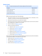
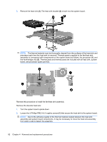
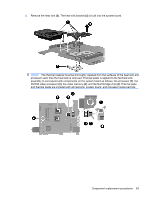
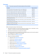
Fan/heat sink assembly Description UMA heat sink (includes heat sink retention clip and replacement thermal material) Discrete Heat sink (includes heat sink retention clip and replacement thermal material) Spare part number 531210-001 531220-001 Before removing the heat sink, follow these steps: 1. Shut down the computer. If you are unsure whether the computer is off or in Hibernation, turn the computer on, and then shut it down through the operating system. 2. Disconnect all external devices connected to the computer. 3. Disconnect the power from the computer by first unplugging the power cord from the AC outlet and then unplugging the AC adapter from the computer. 4. Remove the battery (see Battery on page 47). 5. Remove the following components: a. Optical drive (see Optical drive on page 53) b. Hard drive (see Hard drive on page 56) c. Keyboard (see Keyboard on page 60) d. Keyboard cover (see Keyboard cover on page 63) e. Display assembly (see Display assembly on page 66) f. Top cover (see Top cover on page 72) g. System board (see System board on page 76) Remove the UMA heat sink: 1. Turn the system board upside down. CAUTION: Loosen the screws in the order indicated on the fan/heat sink assembly to ensure consistent pressure over the processor board. 2. Loosen the 3 Phillips PM2.0×5.0 captive screws (1) that secure the fan/heat sink assembly to the system board. NOTE: Due to the adhesive quality of the thermal material located between the heat sink assembly and system board components, it may be necessary to move the heat sink assembly from side to side to detach the assembly. Component replacement procedures 81
-
 1
1 -
2
-
3
-
4
-
5
-
6
-
7
-
8
-
9
-
10
-
11
-
12
-
13
-
14
-
15
-
16
-
17
-
18
-
19
-
20
-
21
-
22
-
23
-
24
-
25
-
26
-
27
-
28
-
29
-
30
-
31
-
32
-
33
-
34
-
35
-
36
-
37
-
38
-
39
-
40
-
41
-
42
-
43
-
44
-
45
-
46
-
47
-
48
-
49
-
50
-
51
-
52
-
53
-
54
-
55
-
56
-
57
-
58
-
59
-
60
-
61
-
62
-
63
-
64
-
65
-
66
-
67
-
68
-
69
-
70
-
71
-
72
-
73
-
74
-
75
-
76
-
77
-
78
-
79
-
80
-
81
-
82
-
83
-
 84
84 -
 85
85 -
 86
86 -
 87
87 -
 88
88 -
 89
89 -
 90
90 -
 91
91 -
 92
92 -
 93
93 -
 94
94 -
95
-
96
-
97
-
98
-
99
-
100
-
101
-
102
-
103
-
104
-
105
-
106
-
107
-
108
-
109
-
110
-
111
-
112
-
113
-
114
-
115
-
116
-
117
-
118
-
119
-
120
-
121
-
122
-
123
-
124
-
125
-
126
-
127
-
128
-
129
-
130
-
131
-
132
-
133
-
134
-
135
-
136
-
137
-
138
-
139
-
140
-
141
-
142
-
143
-
144
 |
 |