HP Presario M2000 HP Pavilion ze2000 Notebook PC, Compaq Presario M2000 Notebo - Page 145
Battery Connector Board, Battery Connector Board Spare Part Number Information
 |
View all HP Presario M2000 manuals
Add to My Manuals
Save this manual to your list of manuals |
Page 145 highlights
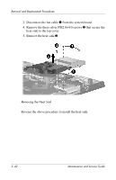
Removal and Replacement Procedures 5.18 Battery Connector Board Battery Connector Board Spare Part Number Information Battery connector board 382413-001 1. Prepare the computer for disassembly (Section 5.3) and remove the following components: a. Hard drive (Section 5.4) b. Optical drive (Section 5.6) c. Memory module compartment cover (Section 5.7) d. Mini PCI compartment cover (Section 5.8) e. Keyboard cover (Section 5.9) f. Keyboard (Section 5.11) g. Display assembly (Section 5.12) h. Base enclosure (Section 5.13) 2. Turn the top cover top-side up with the front panel toward you. Maintenance and Service Guide 5-47
-
 1
1 -
2
-
3
-
4
-
5
-
6
-
7
-
8
-
9
-
10
-
11
-
12
-
13
-
14
-
15
-
16
-
17
-
18
-
19
-
20
-
21
-
22
-
23
-
24
-
25
-
26
-
27
-
28
-
29
-
30
-
31
-
32
-
33
-
34
-
35
-
36
-
37
-
38
-
39
-
40
-
41
-
42
-
43
-
44
-
45
-
46
-
47
-
48
-
49
-
50
-
51
-
52
-
53
-
54
-
55
-
56
-
57
-
58
-
59
-
60
-
61
-
62
-
63
-
64
-
65
-
66
-
67
-
68
-
69
-
70
-
71
-
72
-
73
-
74
-
75
-
76
-
77
-
78
-
79
-
80
-
81
-
82
-
83
-
84
-
85
-
86
-
87
-
88
-
89
-
90
-
91
-
92
-
93
-
94
-
95
-
96
-
97
-
98
-
99
-
100
-
101
-
102
-
103
-
104
-
105
-
106
-
107
-
108
-
109
-
110
-
111
-
112
-
113
-
114
-
115
-
116
-
117
-
118
-
119
-
120
-
121
-
122
-
123
-
124
-
125
-
126
-
127
-
128
-
129
-
130
-
131
-
132
-
133
-
134
-
135
-
136
-
137
-
138
-
139
-
 140
140 -
 141
141 -
 142
142 -
 143
143 -
 144
144 -
 145
145 -
 146
146 -
 147
147 -
 148
148 -
 149
149 -
 150
150 -
151
-
152
-
153
-
154
-
155
-
156
-
157
-
158
-
159
-
160
-
161
-
162
-
163
-
164
-
165
-
166
-
167
-
168
-
169
-
170
-
171
-
172
-
173
-
174
-
175
-
176
-
177
-
178
-
179
-
180
-
181
-
182
-
183
-
184
-
185
-
186
-
187
-
188
-
189
-
190
-
191
-
192
-
193
-
194
-
195
-
196
-
197
-
198
-
199
-
200
-
201
-
202
-
203
-
204
-
205
-
206
-
207
-
208
-
209
-
210
-
211
-
212
-
213
-
214
-
215
-
216
-
217
 |
 |

Removal and Replacement Procedures
Maintenance and Service Guide
5–47
5.18
Battery Connector Board
1. Prepare the computer for disassembly (
Section 5.3
)
and remove the following components:
a.
Hard drive (
Section 5.4
)
b.
Optical drive (
Section 5.6
)
c.
Memory module compartment cover (
Section 5.7
)
d.
Mini PCI compartment cover (
Section 5.8
)
e.
Keyboard cover (
Section 5.9
)
f.
Keyboard (
Section 5.11
)
g.
Display assembly (
Section 5.12
)
h.
Base enclosure (
Section 5.13
)
2. Turn the top cover top-side up with the front panel
toward you.
Battery Connector Board Spare Part Number Information
Battery connector board
382413-001