HP ProBook 5330m HP ProBook 5330m Notebook PC - Maintenance and Service Guide - Page 74
System board - i5
 |
View all HP ProBook 5330m manuals
Add to My Manuals
Save this manual to your list of manuals |
Page 74 highlights
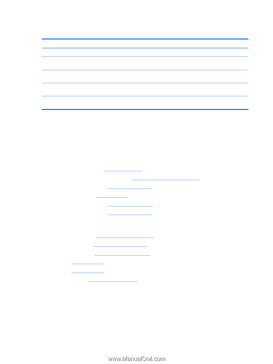
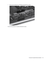
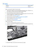
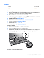
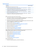
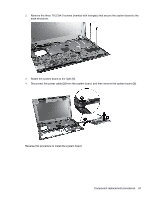
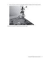
System board Description Spare part number System board (includes replacement thermal material) ● Includes Intel Core i3-2310M, Dual-Core, 2.10 GHz, 3 MB L3 cache, 4 threads (35 W)-for all countries except Russia and the People's Republic of China 650402-001 ● Includes Intel Core i5-2520M, Dual-Core, 2.50 GHz (Turbo up to 3.20 GHz), 3 MB L3 cache, 650403-001 4 threads (35 W)-for all countries except Russia and the People's Republic of China ● Includes Intel Core i3-2310M, Dual-Core, 2.10 GHz, 3 MB L3 cache, 4 threads (35 W)--for Russia and the People's Republic of China only 656796-001 ● Includes Intel Core i5-2520M, Dual-Core, 2.50 GHz (Turbo up to 3.20 GHz), 3 MB L3 cache, 656797-001 4 threads (35 W) --for Russia and the People's Republic of China only Before removing the system board, follow these steps: 1. Shut down the computer. If you are unsure whether the computer is off or in Hibernation, turn the computer on, and then shut it down through the operating system. 2. Disconnect all external devices connected to the computer. 3. Disconnect the power from the computer by first unplugging the power cord from the AC outlet and then unplugging the AC adapter from the computer. 4. Remove the battery (see Battery on page 36). 5. Remove the service access cover (see Service access cover on page 38). 6. Remove the keyboard (see Keyboard on page 50). 7. Remove the fan (see Fan on page 53). 8. Remove the top cover (see Top cover on page 55). 9. Remove the speakers (see Speakers on page 65). When replacing the system board, be sure that the following components are removed from the defective system board and installed on the replacement system board: ● Memory module (see Memory module on page 40) ● WLAN module (see WLAN module on page 41) ● WWAN module (see WWAN module on page 44) ● SIM (see SIM on page 39) ● Fan (see Fan on page 53) ● RTC battery (see RTC battery on page 64) Remove the system board: 1. Position the computer right-side up, with the front toward you. 66 Chapter 4 Removal and replacement procedures
-
 1
1 -
2
-
3
-
4
-
5
-
6
-
7
-
8
-
9
-
10
-
11
-
12
-
13
-
14
-
15
-
16
-
17
-
18
-
19
-
20
-
21
-
22
-
23
-
24
-
25
-
26
-
27
-
28
-
29
-
30
-
31
-
32
-
33
-
34
-
35
-
36
-
37
-
38
-
39
-
40
-
41
-
42
-
43
-
44
-
45
-
46
-
47
-
48
-
49
-
50
-
51
-
52
-
53
-
54
-
55
-
56
-
57
-
58
-
59
-
60
-
61
-
62
-
63
-
64
-
65
-
66
-
67
-
68
-
 69
69 -
 70
70 -
 71
71 -
 72
72 -
 73
73 -
 74
74 -
 75
75 -
 76
76 -
 77
77 -
 78
78 -
 79
79 -
80
-
81
-
82
-
83
-
84
-
85
-
86
-
87
-
88
-
89
-
90
-
91
-
92
-
93
-
94
-
95
-
96
-
97
-
98
-
99
-
100
-
101
-
102
-
103
-
104
-
105
-
106
-
107
-
108
-
109
-
110
-
111
-
112
-
113
-
114
-
115
-
116
-
117
-
118
-
119
-
120
-
121
-
122
-
123
-
124
-
125
-
126
-
127
-
128
-
129
 |
 |