HP ProLiant DL185 HP ProLiant DL185 Generation 5 Server Maintenance and Servic - Page 69
Connectors, Switches, and LEDs, Connectors and Components, Front Panel Components - g5 manual
 |
View all HP ProLiant DL185 manuals
Add to My Manuals
Save this manual to your list of manuals |
Page 69 highlights
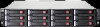
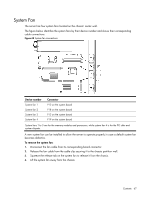
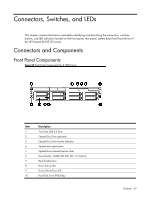
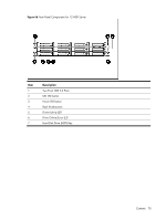
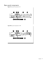
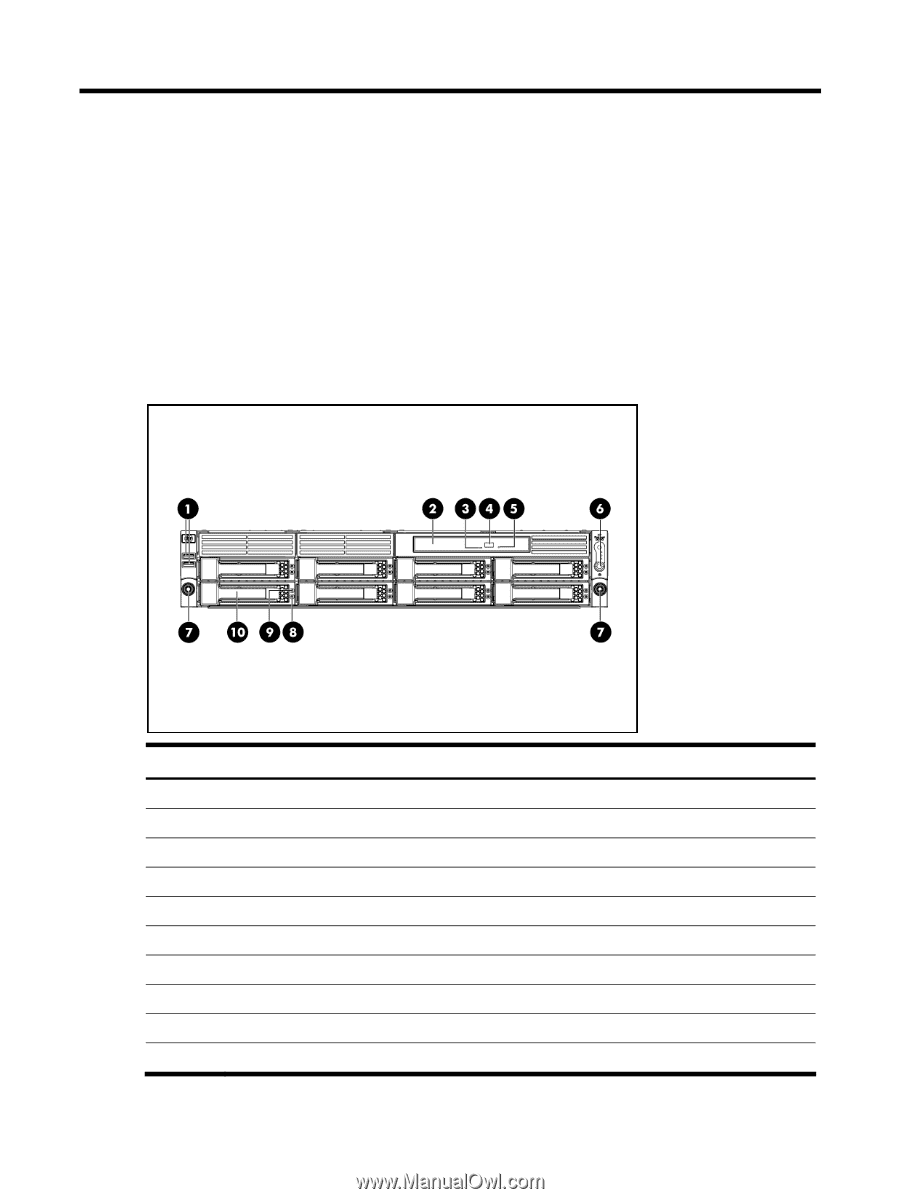
Connectors, Switches, and LEDs This chapter contains illustrations and tables identifying and describing the connectors, switches, buttons, and LED indicators located on the front panel, rear panel, system board and hard drives of the HP ProLiant DL185 G5 server. Connectors and Components Front Panel Components Figure 65 Front Panel Components for 8 HDD Server Item 1 2 3 4 5 6 7 8 9 10 Description Two Front USB 2.0 Ports Optical Disc Drive (optional) Optical Disc Drive Activity Indicator Optical drive eject button Optical Drive Manual Ejection Hole Power button, Health/UID LED, NIC 1/2 Activity Rack thumbscrews Drive Activity LED Drive Online/Error LED Hard Disk Drive (HDD) Bay Contents 69
-
 1
1 -
2
-
3
-
4
-
5
-
6
-
7
-
8
-
9
-
10
-
11
-
12
-
13
-
14
-
15
-
16
-
17
-
18
-
19
-
20
-
21
-
22
-
23
-
24
-
25
-
26
-
27
-
28
-
29
-
30
-
31
-
32
-
33
-
34
-
35
-
36
-
37
-
38
-
39
-
40
-
41
-
42
-
43
-
44
-
45
-
46
-
47
-
48
-
49
-
50
-
51
-
52
-
53
-
54
-
55
-
56
-
57
-
58
-
59
-
60
-
61
-
62
-
63
-
 64
64 -
 65
65 -
 66
66 -
 67
67 -
 68
68 -
 69
69 -
 70
70 -
 71
71 -
 72
72 -
 73
73 -
 74
74 -
75
-
76
-
77
-
78
-
79
-
80
-
81
-
82
-
83
-
84
-
85
-
86
-
87
-
88
-
89
-
90
-
91
-
92
-
93
-
94
-
95
-
96
-
97
-
98
-
99
-
100
-
101
-
102
-
103
 |
 |
Contents 69
Connectors, Switches, and LEDs
This chapter contains illustrations and tables identifying and describing the connectors, switches,
buttons, and LED indicators located on the front panel, rear panel, system board and hard drives of
the HP ProLiant DL185 G5 server.
Connectors and Components
Front Panel Components
Figure 65
Front Panel Components for 8 HDD Server
Item
Description
1
Two Front USB 2.0 Ports
2
Optical Disc Drive (optional)
3
Optical Disc Drive Activity Indicator
4
Optical drive eject button
5
Optical Drive Manual Ejection Hole
6
Power button, Health/UID LED, NIC 1/2 Activity
7
Rack thumbscrews
8
Drive Activity LED
9
Drive Online/Error LED
10
Hard Disk Drive (HDD) Bay