HP ProLiant DL185 Dynamic Power Capping TCO and Best Practices White Paper (EM - Page 4
At the Rack Level, Time hrs, Power KW
 |
View all HP ProLiant DL185 manuals
Add to My Manuals
Save this manual to your list of manuals |
Page 4 highlights
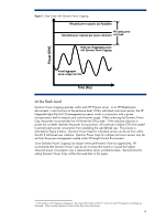
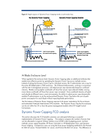
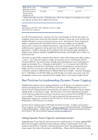
Power (KW) Figure 1. Data Center with Dynamic Power Capping Allocated power capacity (per faceplate) Allocated power Allocated power capacity (per power calculator) reclaimed Hard cap of aggregate power with Dynamic Power Capping Actual aggregate power usage over time Time (hrs) At the Rack Level Dynamic Power Capping operates within each HP ProLiant server. In an HP BladeSystem environment, it also functions at the enclosure level. Within individual rack-mount servers, the HP Integrated Lights-Out (iLO 2) management processor works in conjunction with a power microprocessor both to measure and control power usage. When enforcing the Dynamic Power Cap, the power microcontroller first will lower the CPU p-state.3 If the required reduction in power has not been reached, the power microprocessor will continue to reduce CPU clock speed to prevent peak power consumption from exceeding the user-defined cap. This process is illustrated in Figure 2 below. Dynamic Power Caps for individual servers can be set from within the iLO 2 Advanced user interface. Dynamic Power Caps for multiple rack-mount servers may be set from the power management module within HP Insight Control Environment. Since Dynamic Power Capping can impact server performance if set too aggressively, HP recommends that Dynamic Power Caps be set at values that match or exceed the highest observed power consumption over a representative server workload sample. Best practices for setting Dynamic Power Caps will be discussed later in this paper. 3 A CPU p-state is a CPU frequency/voltage pair. By increase the P-state from P0 to P1 to P2, etc. both CPU frequency and voltage are decreased. When computers operate at a lower p-state, they consume less power. 4
-
 1
1 -
 2
2 -
 3
3 -
 4
4 -
 5
5 -
 6
6 -
 7
7 -
 8
8 -
 9
9 -
 10
10 -
11
-
12
-
13
-
14
-
15
 |
 |
