HP ProLiant DL185 Dynamic Power Capping TCO and Best Practices White Paper (WW - Page 11
Update server BIOS, iLO firmware, Onboard Administrator, circuit and PDUs to which they are attached.
 |
View all HP ProLiant DL185 manuals
Add to My Manuals
Save this manual to your list of manuals |
Page 11 highlights
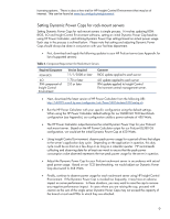
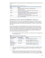
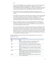
each. • Next, use the HP BladeSystem Sizer to calculate how many servers will fit in each enclosure, using the given power budget. For the BL460c G1 configuration used in our TCO benchmarking (see Appendix), the BladeSystem Sizer indicates that 10 BL460 G1 servers will fit in each c7000 enclosure (20 total). Depending on the number of blades that will fit into the enclosure, the IT department may want to adjust the "enclosure per circuit" goal. • Deploy additional enclosures as appropriate and set Dynamic Power Caps for each enclosure. Insert up to the number of blades specified by the HP BladeSystem Sizer in each enclosure. • Using Insight Control Environment, observe peak power usage for a period of time that aligns to the enclosure's application duty cycle. Depending on the applications in question, this duty cycle could be as short as a few days or as long as a calendar quarter. HP recommends collecting and observing data for at least one week to ensure that the peak value observed represents the true peak power usage for the c7000 enclosure in question. • Based on observed power usage, continue to add more blades to the c7000 enclosure until power consumption approaches the 4300 Watt Dynamic Power Cap. Based on our TCO benchmark comparison, we were able to fit 14 BL460c G1 servers in each enclosure for a total of 28 servers for the 8.6 kW circuit. . • Finally, continue to observe power usage for each c7000 enclosure using HP Insight Control Environment. If the Dynamic Power Cap for the enclosure is invoked too frequently, it may have an adverse impact on server performance. In these situations, you may want to remove blades from the enclosure or raise the enclosure Dynamic Power Cap to remove any negative performance impact. In cases where you are raising the cap, proceed with caution as the sum of the single enclosure Dynamic Power Caps may not exceed the capacity of the branch circuit and PDUs to which they are attached. The following table summarizes the best practice for establishing Dynamic Power Caps for HP BladeSystem enclosures. Table 7. Steps to Best Practices with ServerBlade Servers Step Step 1 Step 2 Step 3 Step 4 Step 5 Action Update server BIOS, iLO firmware, Onboard Administrator firmware, and Insight Control Environment software. Work with facilities to size available electrical (and cooling) capacity and to establish a goal for the number of enclosures per circuit. Use the HP BladeSystem Sizer to estimate the number of blades that can be safely added to each enclosure without performance impact. Observe power usage using Insight Control Environment for a complete application duty cycle and either adjust Dynamic Power Cap for c7000 enclosure based on peak power usage or add additional blades to the enclosure. Continue to observe power usage and adjust if Dynamic Power Cap is invoked frequently. 11
-
 1
1 -
2
-
3
-
4
-
5
-
 6
6 -
 7
7 -
 8
8 -
 9
9 -
 10
10 -
 11
11 -
 12
12 -
 13
13 -
 14
14 -
 15
15
 |
 |
