HP ProLiant DL185 Dynamic Power Capping TCO and Best Practices White Paper (WW - Page 5
At Blade Enclosure Level
 |
View all HP ProLiant DL185 manuals
Add to My Manuals
Save this manual to your list of manuals |
Page 5 highlights
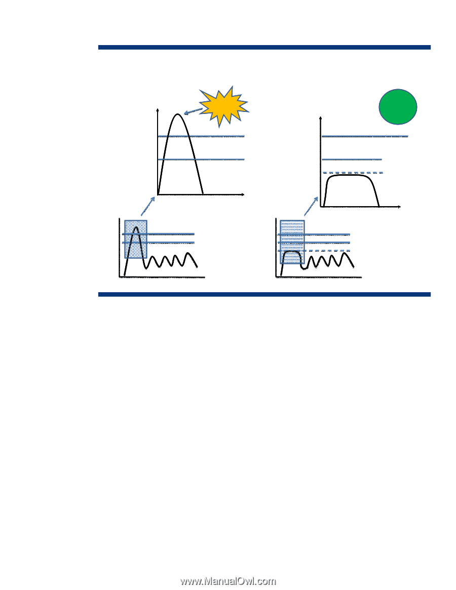
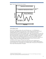
Figure 2. Rapid response of Dynamic Power Capping avoids circuit breaker trips No Dynamic Power Capping Dynamic Power Capping Enabled Circuit trips Total circuit capacity Circuit Safe Total circuit capacity De‐rated circuit capacity 0 Capacity Time (seconds) 5 10 Capacity Total circuit capacity De‐rated circuit capacity Time De‐rated circuit capacity Dynamic Power Cap Time (seconds) 0 5 10 Total circuit capacity De‐rated circuit capacity Dynamic Power Cap Time At Blade Enclosure Level When applied at the enclosure level, Dynamic Power Capping takes on additional attributes that enable more effective power by spreading the Dynamic Power Cap across multiple servers.. Instead of setting the Dynamic Power Cap for individual servers, the IT administrator sets a cap for the entire HP BladeSystem c7000 enclosure. The Onboard Administrator, working in conjunction with the iLO 2 management processor, will adjust power caps dynamically based on workload intensity. Blades running lighter workloads will have their power caps reduced; blades running more intense workloads will have their power caps increased. Since workload intensity will peak and subside at different times in most environments, the ability to adjust power caps dynamically enables IT administrators to set the enclosure-level Dynamic Power Cap below the sum of peak power consumption for each blade without impacting blade performance. The first release of Dynamic Power Capping requires N+N power redundancy for the enclosure and redundant Onboard Administrator (OA) modules. The Dynamic Power Cap for the enclosure can be set within the OA or from the power management module within HP Insight Control Environment. Dynamic Power Capping TCO analysis This section discusses the TCO benefits customers can anticipate following a successful implementation of Dynamic Power Capping. The analysis compares the number of servers that can be allocated to a typical 30Amp 3-phase circuit (208V) when budgeting power via three methods: power supply faceplate, HP Power Calculator or HP BladeSystem Sizer, and Dynamic Power 5
-
 1
1 -
 2
2 -
 3
3 -
 4
4 -
 5
5 -
 6
6 -
 7
7 -
 8
8 -
 9
9 -
 10
10 -
 11
11 -
12
-
13
-
14
-
15
 |
 |