HP ProLiant SL160s HP ProLiant SL160s G6 Server Installation Instructions - Page 5
Installing the Hard Disk Drive, Installing the Memory Module
 |
View all HP ProLiant SL160s manuals
Add to My Manuals
Save this manual to your list of manuals |
Page 5 highlights
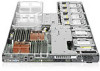
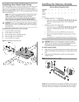
Installing the Hard Disk Drive One SL160s G6 server tray can accommodate up to 6 LFF SATA, 4 LFF SAS, or 8 SFF SATA/SAS Non Hot-Plug hard disk drives, and the chassis can accommodate 4 server trays for up to 24 LFF SATA or 32 SFF Non Hot-Plug hard disk drives. The server supports both SAS and SATA hard disk drives. NOTE: For specific supported hard drive configurations and cable routing, refer to HP ProLiant SL160s G6 Server Maintenance and Service Guide located on the HP website: http://www.hp.com/support/ProLiant_SL160sG6_MSG_en CAUTION: Drives can be damaged by static electricity. Before handling drives, touch an unpainted metal surface to discharge static electricity. To install the LFF hard disk drive in the server tray: 1. Unlock the HDD carrier latches. 2. Lift the HDD carrier handle up. 3. Insert the HDD carrier and align the pins. 4. Press the HDD carrier handle down. 5. Lock the HDD carrier latches. Figure 6 Installing the hard disk drive Installing the Memory Module Memory Module Population Order Population A B C D E F GH I order Memory 3 6 9 2 5 8 1 4 7 Socket NOTES: • Installation guide for 1P configuration: o Follow the sequence of 3A, 6B, 9C, 2D, 5E, 8F, 1G, 4H, and 7I for the corresponding processor when installing the memory. • Installation guide for 2P configuration: o Follow the sequence of 3A, 6B, 9C, 2D, 5E, 8F, 1G, 4H, and 7I for the corresponding processor when installing the memory. o Install at least one memory DIMM for each processor. o The memory quantity installed for each processor can be different. o The DIMM slot 1 should be the closest one of the processor. CAUTION: DIMMs can be damaged by improper handling. Always use an anti-static wrist strap and grounding mat, and discharge static electricity before touching DIMMs. To install a memory module: 1. Align the notch on the bottom edge of the module with the keyed surface of the DIMM slot and then press the module fully into the slot. 2. Firmly press the holding clips inward to secure the memory module in place. Figure 7 Installing the memory module DIMM slots are structured to ensure proper installation. If you insert a DIMM but it does not fit easily into the slot, you may have inserted it incorrectly. Reverse the orientation of the DIMM and insert it again. 5
-
 1
1 -
 2
2 -
 3
3 -
 4
4 -
 5
5 -
 6
6 -
 7
7 -
 8
8
 |
 |
