HP SW TL881 DLT Mini-Lib/1 Compaq TL881 MiniLibrary Drive Upgrade Procedure (M - Page 17
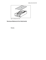
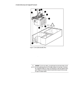
Installing the Second Tape Drive, Removing and, Replacing the Drive Caddy Assembly
 |
View all HP SW TL881 DLT Mini-Lib/1 manuals
Add to My Manuals
Save this manual to your list of manuals |
Page 17 highlights
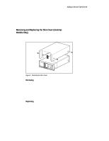
8 TL881 MiniLibrary Drive Upgrade Procedure Installing the Second Tape Drive Do the following steps to install the second tape drive. 1. Remove the four 6-32 sems pan-head Phillips screws (7) that hold the blank panel in place in the drive caddy assembly; there are two on the top of the assembly (Figure 4) and two on the bottom of the assembly. 2. Slide the blank panel out of the drive caddy assembly. 3. Disconnect the RS-422 cable toward the front on the top of the drive, and lift the cable clear of the cable clamps; set it aside. 4. Install the door lever on the flatted shaft at the bottom of the drive. 5. Slide the drive (6) into the drive caddy assembly; position the drive so the threaded holes in the top and bottom of the drive are aligned with the screws holes. 6. Install the four 6-32 sems pan-head Phillips screws that were removed in Step 1. 7. Connect the unused connector on the power Y-cable to the drive just installed. 8. Connect the unused connector on the SCSI cable to the drive just installed. 9. Install the RS-422 cable supplied with the kit, sliding it under the clamps so that the connector is adjacent to the connector on top of the new drive. 10. Install the RS-422 cable removed in Step 3 over the top of the new RS422 cable so that the connector is adjacent to the connector on top of the original drive. 11. Connect the RS-422 cables to the connectors on the top of the drives, through the holes in the top of the drive caddy assembly. 12. Replace the drive caddy assembly as described in Removing and Replacing the Drive Caddy Assembly.
-
 1
1 -
2
-
3
-
4
-
5
-
6
-
7
-
8
-
9
-
10
-
11
-
 12
12 -
 13
13 -
 14
14 -
 15
15 -
 16
16 -
 17
17 -
 18
18 -
 19
19
 |
 |