HP Scitex FB750 Site Preparation Guide - Page 11
Floor requirements
 |
View all HP Scitex FB750 manuals
Add to My Manuals
Save this manual to your list of manuals |
Page 11 highlights
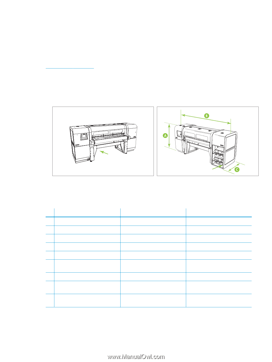
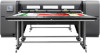
Floor requirements When planning the print production area, it is important to ensure that the floor surface is solid, smooth, level, and free from any holes or indentations. Floor covering material should be durable and easy to clean. Floor load-bearing capabilities in the print production area are an essential consideration. This will require consulting the structural engineer for the building in which the printer is to be installed. See the Specifications on page 14 for the shipping and assembled weights of the printer. During installation, the printer and media tables will be leveled to ensure accurate media feeding. The printer and table feet can be adjusted to compensate for a maximum floor slope (elevation change) of 5.6 cm (2.2 in) over the printer width, and 5.1 cm (2.0 in) over the printer depth. Figure 2-1 Features and dimensions (FB550 shown, FB750 similar) Service-end User-end Power cord inlet Input side Table 2-2 Printer and table dimensions A Height B Width C Depth without tables D Input table depth E Output table depth F, Accessory table depth G H Table width I Depth with input and output tables installed J Depth with input, output, and accessory tables installed FB550 153 cm (60 in) 325 cm (128 in) 141 cm (56 in) 52 cm (21 in) 89 cm (35 in) 165 cm (65 in) 175 cm (69 in) 282 cm (111 in) 612 cm (241 in) Vacuum system auxiliary power outlet Output side FB750 153 cm (60 in) 412 cm (162 in) 141 cm (56 in) 52 cm (21 in) 81 cm (32 in) 89 cm (35 in) 262 cm (103 in) 246 cm (97 in) 411 cm (162 in) ENWW Facility requirements 5
-
 1
1 -
2
-
3
-
4
-
5
-
 6
6 -
 7
7 -
 8
8 -
 9
9 -
 10
10 -
 11
11 -
 12
12 -
 13
13 -
 14
14 -
 15
15 -
 16
16 -
17
-
18
-
19
-
20
-
21
-
22
-
23
-
24
 |
 |