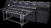
HP Scitex FB910 HP Scitex FB910 Printer Series - Vacuum Pressure System Guide - Page 3
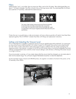
How Pressure is Used, Components of the Vacuum/Pressure System - ink filters
 |
View all HP Scitex FB910 manuals
Add to My Manuals
Save this manual to your list of manuals |
Page 3 highlights
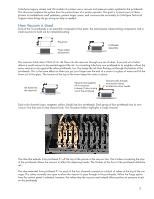
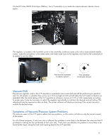
How Pressure is Used Air pressure is used for two purposes. The first and more frequent purpose is as part of the Purge cleaning process. When pressure is applied to the reservoirs, air displaces the ink. The ink has nowhere to go but out the inkjet nozzles on the bottom of the printheads. The ink under air pressure will try to dislodge any partially solidified ink or foreign particles that may have accumulated inside or around the inkjet nozzles. If an individual jet on the printhead has stopped firing, the purge-followed by appropriate cleaning of the residual ink from the bottom of the printhead- can restore that jet to working order. The second purpose of pressure is to move all the ink (or HP printhead flush solution) out of the printheads as part of a maintenance or service procedure. This is really no different than the cleaning Purge described above, but it continues for a sustained period of time until all of the liquid has been pushed out of the reservoir and piezo inkjet printing mechanism. Air pressure uses the same tubes shown in the photograph above. The valve, not visible in the picture, stops the vacuum and allows the pressure to enter the tubes instead. Components of the Vacuum/Pressure System The preceding pages have already described the tubing used at the printheads. The remaining parts of the Vacuum/ Pressure system are as follows: Valves and Manifold Long Tube for Vacuum This tube is the same type of tube found at the printheads. This long length runs from the V/P Assembly up to the valves on the carriage. The long tubes for vacuum and pressure connect on one side of this assembly. The valves switch between vacuum and pressure. The normal state is to allow vacuum to apply to the printheads. Vacuum/Pressure Assembly Contains the pumps that create the vacuum and pressure; the vacuum regulator, and vacuum switch. The blue cup-like component is the vacuum reservoir. It looks like a filter housing, but it is not. Long Tube for Pressure This tube is skinnier and more rigid than the vacuum tube. This long length runs from the V/P Assembly up to the valves on the carriage. Short Tubes to Printheads Once past the valves, a single tube for each color channel connects to the printhead. This tube is normally be used for vacuum, but is used for pressure when a Purge or other printer function requires it. 3
-
 1
1 -
 2
2 -
 3
3 -
 4
4 -
 5
5 -
 6
6 -
 7
7
 |
 |
