HP Scitex FB910 HP Scitex FB910 Printer Series - Vacuum Pressure System Guide - Page 4
Filters, Setting and Adjusting the Vacuum Level
 |
View all HP Scitex FB910 manuals
Add to My Manuals
Save this manual to your list of manuals |
Page 4 highlights
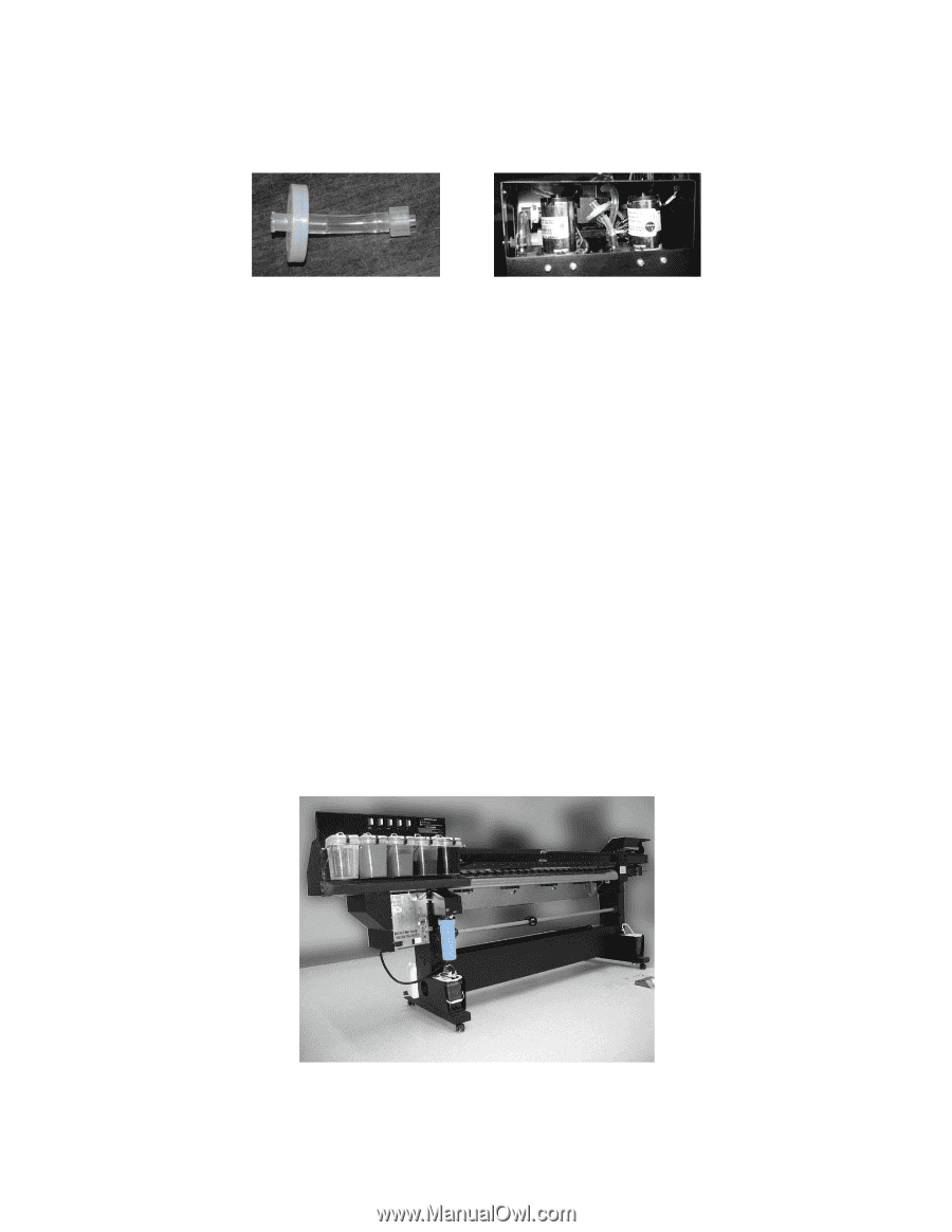
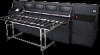
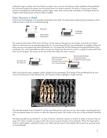
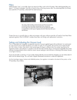
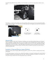
Filters While the blue "cup" is not a filter, there are several air filters used on the VP system. These disk-shaped filters are about 1" (2.5cm) in diameter. One filter is found in-line on the long vacuum tube. The remaining filters (2 of them) are inside the V/P assembly, underneath the metal enclosure. Two views of the air filters used in the Vacuum/Pressure assembly. On the left is the in-line filter, removed from the vacuum line. On the right is the input filter inside of the V/P assembly. Not visible is another filter on the vacuum regulator. All of the filters have the same specification. Printers that are in unusually dusty or other environments with many airborne particles will need to have these filters replaced regularly. Filter kit 0901421 includes three filters with fittings and replacement instructions. Setting and Adjusting the Vacuum Level The V/P assembly has a regulator to adjust the amount of vacuum applied against the printheads. For solvent printers, the nominal vacuum level should be 3.25 inches of water. For UV printers, the nominal vacuum level should be 5.00 inches of water. Note that for both printer types this figure is different than the number specified in the respective printer's User Manual. A variation of ±0.20 from the nominal value is normal and acceptable.The printer software is programmed to know what the correct vacuum settings is and will show a Warning if the actual vacuum is too high or too low. If you do encounter a warning, or if you simply observe that the vacuum level has changed, you can easily adjust it back into the desired range. You will need a regular flat-bladed screwdriver to make the adjustment. On the ColorSpan Legacy Solvent and UVR-UVX printers, the regulator is located on the back of the printer, on the VP assembly, shown below. 4
-
 1
1 -
 2
2 -
 3
3 -
 4
4 -
 5
5 -
 6
6 -
 7
7
 |
 |