HP Server tc2120 HP 2100S SCSI RAID - User Guide (337208-001) - Page 26
Installing the Controller, Layout in About Your New Controller.
 |
View all HP Server tc2120 manuals
Add to My Manuals
Save this manual to your list of manuals |
Page 26 highlights
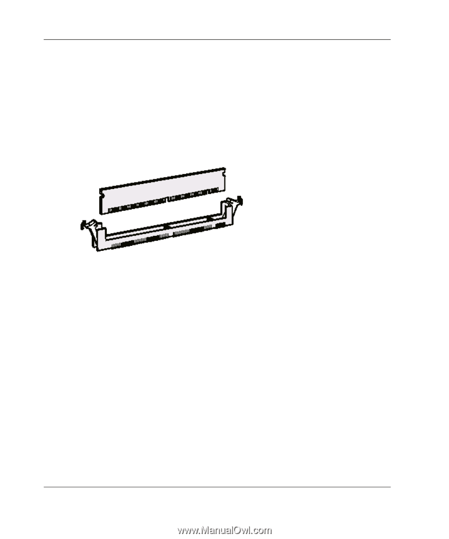
Installing Your Controller To install cache memory modules: 1. Install the modules in the socket as shown. For socket location, refer to "Board Layout" in Chapter 2, "About Your New Controller." Press the DIMM firmly into the socket. Ensure that the clips are engaged in the notches on both sides of the DIMM. 2. To confirm that the modules are properly installed, start SMOR and select the controller to display the amount of cache memory reported. Installing the Controller 1. Connect the computer's disk activity LED cable to connector P6 on the controller. For the location of this connector, refer to "Board Layout" in Chapter 2, "About Your New Controller." 2. Pins 1 and 3 of P6 are connected to +5V and pins 2 and 4 are connected to GND. Ensure that the positive lead of the LED cable (usually a red wire or marked with a red stripe) is attached to pin 1 or 3 and the negative lead (usually a black wire) is attached to pin 2 or 4. 3. If you are using the internal SCSI cable, connect this cable to the controller. 4. Install the controller in an available 32- or 64-bit PCI bus slot and secure the controller bracket to the host system cabinet with the screw provided. 5. In a system with multiple controllers, the controller that has the lowest BIOS ROM address (typically, the lowest numbered PCI slot) will become the booting controller. 3-6 HP 2100S SCSI RAID Controller User Guide
-
 1
1 -
2
-
3
-
4
-
5
-
6
-
7
-
8
-
9
-
10
-
11
-
12
-
13
-
14
-
15
-
16
-
17
-
18
-
19
-
20
-
 21
21 -
 22
22 -
 23
23 -
 24
24 -
 25
25 -
 26
26 -
 27
27 -
 28
28 -
 29
29 -
 30
30 -
 31
31 -
32
-
33
-
34
-
35
-
36
-
37
-
38
-
39
-
40
-
41
-
42
-
43
-
44
-
45
-
46
-
47
-
48
 |
 |