HP Spectre 13-4000 Spectre x360 Convertible PC model numbers 13-4000 through 4 - Page 54
Display assembly
 |
View all HP Spectre 13-4000 manuals
Add to My Manuals
Save this manual to your list of manuals |
Page 54 highlights
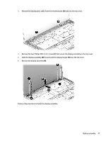
Display assembly Description Spare part number Display assembly: 13.3-in, ultra wide aspect ratio, TouchScreen (includes display panel cable, microphones, hinges, webcam, and wireless antenna cables and transceivers) 13.3-in, QHD, WLED, BrightView (2560×1440), UWVA, 2.55-mm in ash silver finish for use only on computers with model numbers 13-4100 through 13-4199 and equipped with an Intel Core i-7 5500U or Intel Core i-5 5200U processor 833713-001 13.3-in, FHD, WLED, BrightView (1920×1080), UWVA, 2.55-mm in ash silver finish for use only on computers with model numbers 13-4100 through 13-4199 and equipped with an Intel Core i-7 5500U or Intel Core i-5 5200U processor 833712-001 13.3-in, FHD, WLED, BrightView (2560×1440), UWVA, 2.55-mm in natural silver finish for use only on computers with model numbers 13-4100 through 13-4199 and equipped with an Intel Core i-7 6550U, Intel Core i-7 6500U, or Intel Core i-5 6200U processor 828823-001 13.3-in, FHD, WLED, BrightView (1920×1080), UWVA, 2.55-mm in natural silver finish for use only on computers with model numbers 13-4100 through 13-4199 and equipped with an Intel Core i-7 6550U, Intel Core i-7 6500U, or Intel Core i-5 6200U processor 828822-001 13.3-in, QHD, WLED, BrightView (2560×1440), UWVA, 2.55-mm in natural silver finish for use only on computers with model numbers 13-4000 through 13-4099 801496-001 13.3-in, FHD, WLED, BrightView (1920×1080), UWVA, 2.55-mm in natural silver finish for use only on computers with model numbers 13-4000 through 13-4099 801495-001 Before removing the display assembly, follow these steps: 1. Turn off the computer. If you are unsure whether the computer is off or in Hibernation, turn the computer on, and then shut it down through the operating system. 2. Disconnect the power from the computer by unplugging the power cord from the computer. 3. Disconnect all external devices from the computer. 4. Remove the bottom cover (see Bottom cover on page 28), and then remove the following components: a. Remove the battery (see Battery on page 29). b. Remove the fan (see Fan on page 33). c. Remove the system board (see System board on page 38). Remove the display assembly: 1. Open the computer to the interactive position, as shown in the following illustrations. 2. Release the WLAN antenna cables from the retention post (1) built into the top cover. 46 Chapter 5 Removal and replacement procedures
-
 1
1 -
2
-
3
-
4
-
5
-
6
-
7
-
8
-
9
-
10
-
11
-
12
-
13
-
14
-
15
-
16
-
17
-
18
-
19
-
20
-
21
-
22
-
23
-
24
-
25
-
26
-
27
-
28
-
29
-
30
-
31
-
32
-
33
-
34
-
35
-
36
-
37
-
38
-
39
-
40
-
41
-
42
-
43
-
44
-
45
-
46
-
47
-
48
-
 49
49 -
 50
50 -
 51
51 -
 52
52 -
 53
53 -
 54
54 -
 55
55 -
 56
56 -
 57
57 -
 58
58 -
 59
59 -
60
-
61
-
62
-
63
-
64
-
65
-
66
-
67
-
68
-
69
-
70
-
71
-
72
-
73
-
74
-
75
-
76
-
77
-
78
-
79
-
80
-
81
-
82
-
83
-
84
-
85
-
86
-
87
-
88
-
89
-
90
-
91
-
92
-
93
-
94
-
95
-
96
-
97
-
98
-
99
-
100
 |
 |
